
Intelligent switch cabinet

A technology of intelligent switch and cabinet frame, applied in the field of switch cabinet, can solve the problems of safety, hidden danger, inconvenience, etc., and achieve the effect of reducing space occupation, increasing torque, and being easy to use

Active Publication Date: 2020-01-03
河南西之木电气科技有限公司
View PDF5 Cites 4 Cited by
  • Summary
  • Abstract
  • Description
  • Claims
  • Application Information

AI Technical Summary

Problems solved by technology

[0003] Existing switch cabinets include a switch cabinet frame and electrical components installed in the cabinet frame, wherein the front of the switch cabinet is generally hinged with a cabinet door, and the electrical components in the switch cabinet frame are connected, repaired or replaced through the cabinet door, but because The space in the switchgear frame is relatively narrow, which is not conducive to the operation of the user, which is very inconvenient. Moreover, due to the difficulty of maintenance, some switchgears cannot be regularly maintained according to the regulations, so that there are potential safety hazards

Method used


Image

  • Intelligent switch cabinet
  • Intelligent switch cabinet
  • Intelligent switch cabinet

Examples


Embodiment Construction

[0033] The present invention will be described in further detail below in conjunction with the accompanying drawings.

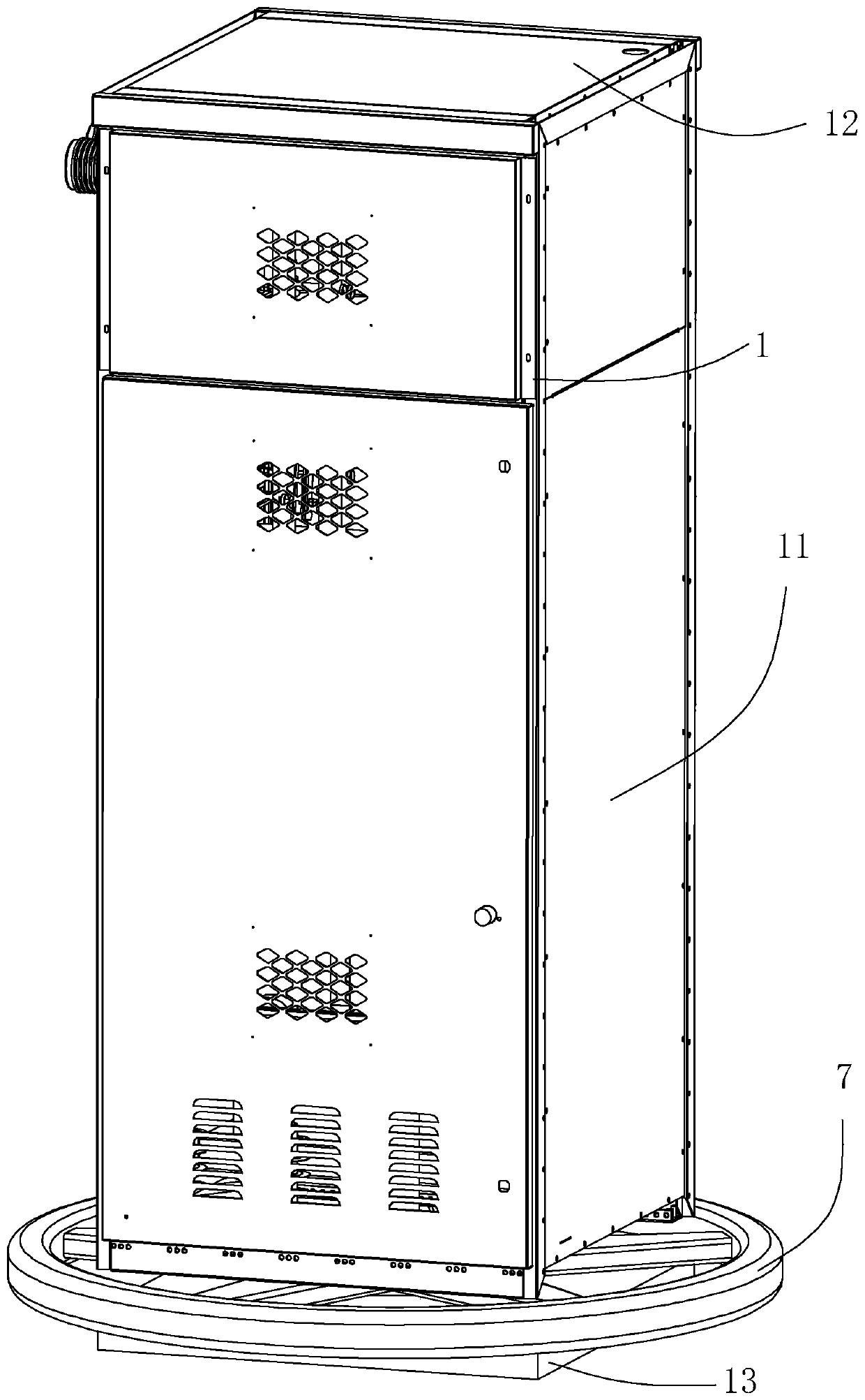
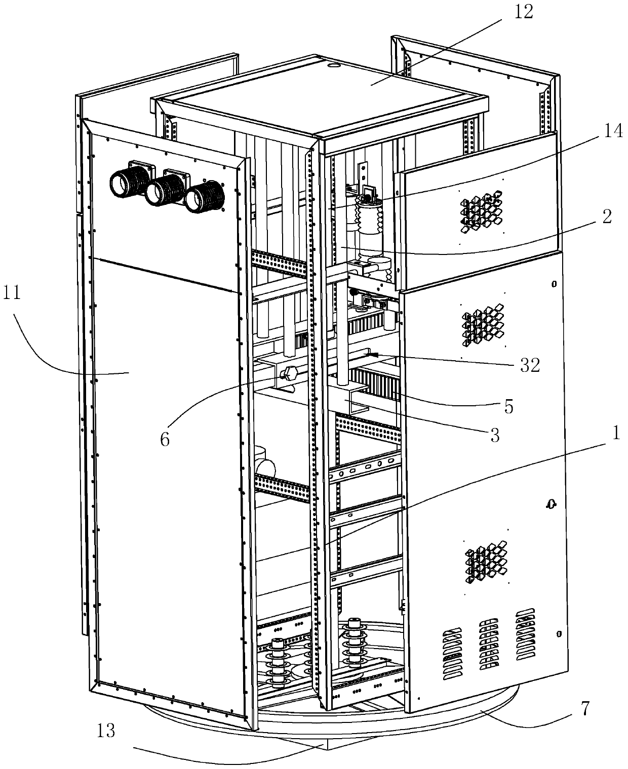
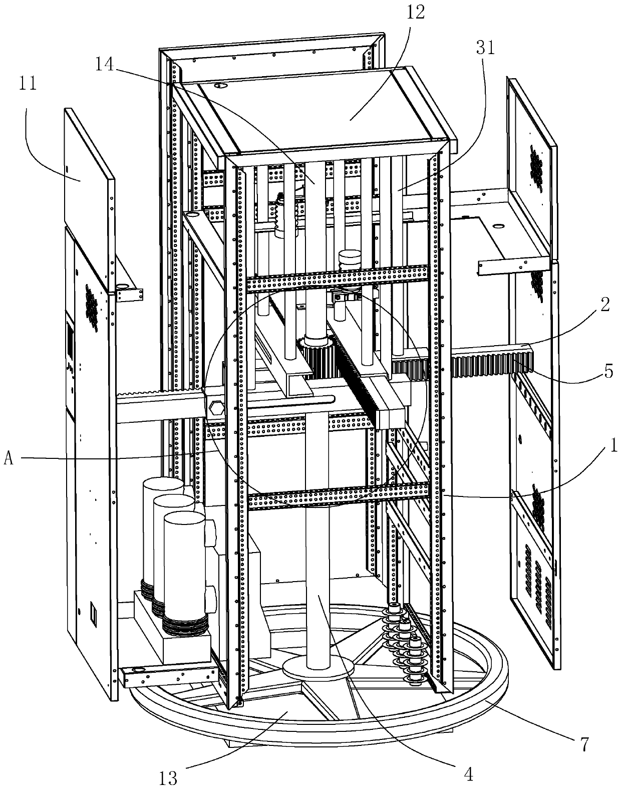
[0034] like Figure 1 to Figure 2 As shown, an intelligent switchgear disclosed by the present invention comprises a rectangular frame-like cabinet frame 1, the top of the cabinet frame 1 is fixed with a top plate 12 covering its upper end surface, and a bottom plate 13 is arranged below the cabinet frame 1. The bottom plate 13 and Cylindrical support columns 14 are fixed between the top plates 12 , and the top plate 12 and the cabinet frame 1 are supported by the support columns 14 . The four sides of the cabinet frame 1 are equipped with cabinet doors 11 covering the sides, and the cabinet doors 11 are flexibly connected with the cabinet frame 1 .

[0035] The lower end surface of the top plate 12 is vertically fixed with a number of load-bearing rods 31, and one end of the load-bearing rods 31 away from the top plate 12 is fixed with a slide rail 3. The s...


PUM


Abstract

The invention relates to an intelligent switch cabinet, which comprises a cabinet frame and a plurality of electrical components installed in the cabinet frame. The four sides of the cabinet frame arecoated with cabinet doors. The cabinet frame is connected in a sliding manner with four groups of supporting rods which are respectively fixed to the cabinet doors. Each supporting rod supports the corresponding cabinet door. The sliding direction of each supporting rod is perpendicular to the plane where the cabinet door connected with the supporting rod is located. A linkage device for drivingthe supporting rods to synchronously slide is arranged in the cabinet frame. Through the arrangement, the linkage device driving the supporting rods to move synchronously enables the supporting rods to move linearly towards the cabinet doors connected with the supporting rods at the same time, the cabinet doors are then driven to move away from the center of the cabinet frame at the same time to expose the electrical components in the switch cabinet, and thus, users can conveniently observe, overhaul, assemble and disassemble the electrical components in the cabinet body from all angles.

Description

technical field [0001] The invention relates to the technical field of switch cabinets, in particular to an intelligent switch cabinet. Background technique [0002] The switch cabinet is a kind of electrical equipment. The outside line of the switch cabinet first enters the main control switch in the cabinet, and then enters the sub-control switch. Each branch is set according to its needs. Such as instruments, automatic controls, motor magnetic switches, various AC contactors, etc., some also have high-voltage room and low-voltage room switch cabinets, high-voltage busbars, such as power plants, etc. load shedding. The main function of the switchgear is to open and close, control and protect electrical equipment during the process of power generation, transmission, distribution and power conversion in the power system. The components in the switch cabinet are mainly composed of circuit breakers, disconnectors, load switches, operating mechanisms, transformers and various...

Claims


Application Information

Patent Timeline
Patent Type & Authority Applications(China)
IPC IPC(8): H02B1/30
CPCH02B1/30
Inventor 栗金停曹坤孙彦丽
Owner 河南西之木电气科技有限公司
Learn More