Transformer substation post insulator cleaning device

A technology for post insulators and cleaning equipment, applied in cleaning methods and utensils, cleaning methods using liquids, cleaning methods using tools, etc., can solve problems such as not easy to remove

Inactive Publication Date: 2020-01-07
国网河南省电力公司邓州市供电公司
View PDF11 Cites 3 Cited by
  • Summary
  • Abstract
  • Description
  • Claims
  • Application Information

AI Technical Summary

Problems solved by technology

However, this invention can only spray water on the post insulator and use a brush to clean it, and it is not easy to remove stubborn pollutants on it

Method used


Image

  • Transformer substation post insulator cleaning device
  • Transformer substation post insulator cleaning device
  • Transformer substation post insulator cleaning device

Examples


Embodiment 1

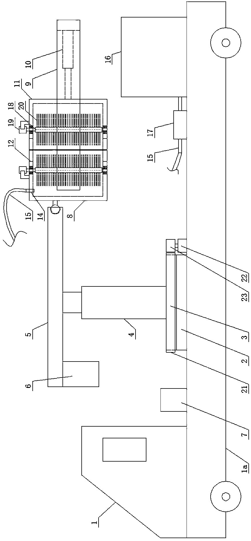
[0042] Such as figure 1 and figure 2 As shown, a substation post insulator cleaning equipment includes a trolley body 1, a circular base 3 is provided on the vehicle plate 1a of the trolley body 1 through a slewing support 2, and a first automatic telescopic Rod 4, horizontal beam 5 is arranged on the first automatic telescopic rod 4, the left end of the beam 5 is provided with a counterweight 6, the right end of the beam 5 is ball-hinged with a cleaning mechanism, the car plate 1a of the trolley body 1 A rotary drive mechanism for controlling the rotation of the base 3 is provided on it, and a control mechanism 7 for controlling the first automatic telescopic rod 4 , the cleaning mechanism and the rotary drive mechanism is provided on the vehicle plate 1 a of the trolley body 1 .

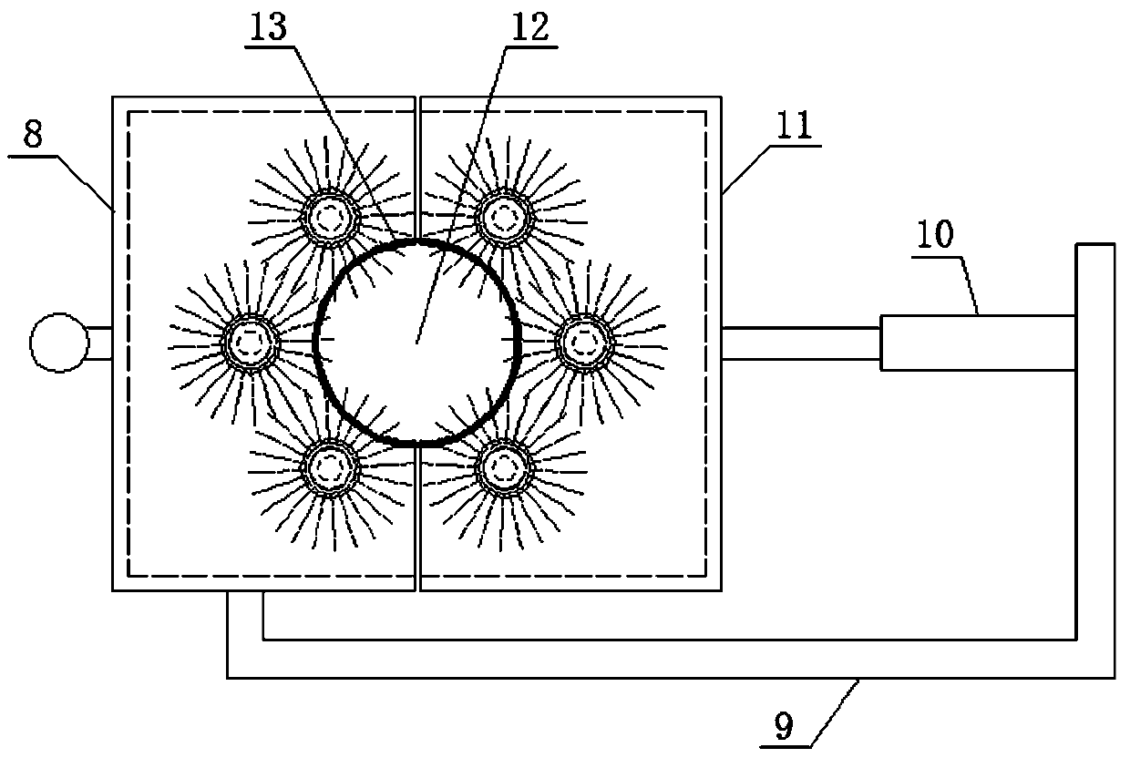
[0043] The cleaning mechanism includes a first half-shell 8 that is ball-hinged to the right end of the beam 5, a half-frame connecting rod 9 is arranged on the side of the first half-shell 8, an...

Embodiment 2

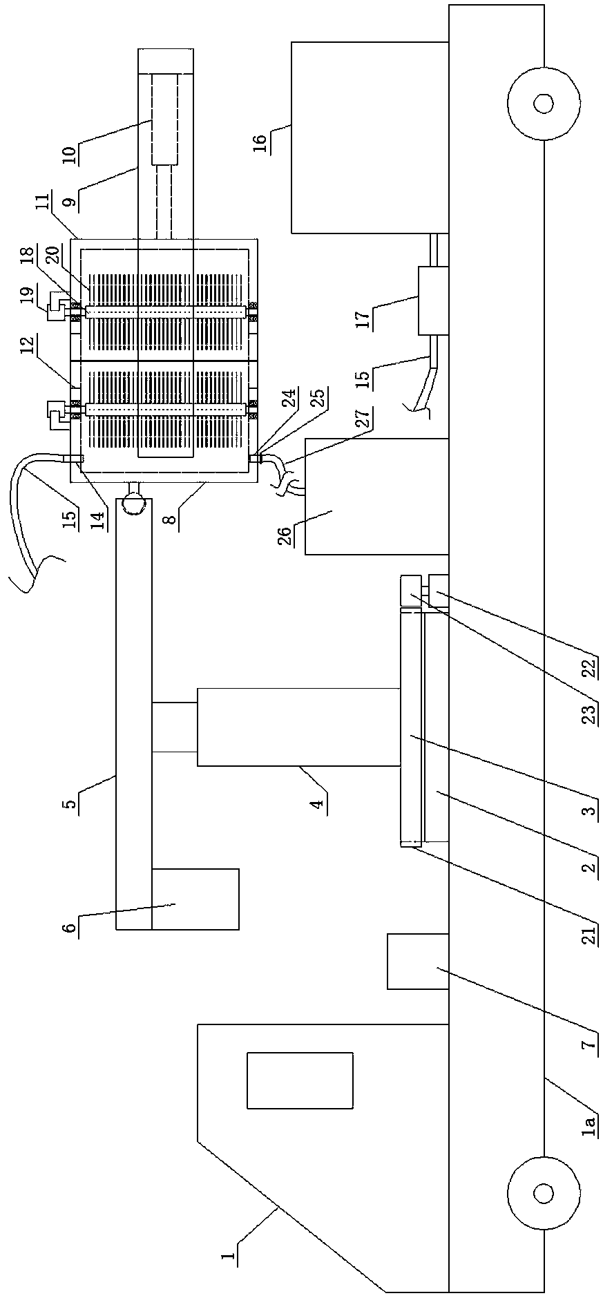
[0052] Such as image 3 and Figure 4 As shown, a substation post insulator cleaning equipment includes a trolley body 1, a circular base 3 is provided on the vehicle plate 1a of the trolley body 1 through a slewing support 2, and a first automatic telescopic Rod 4, horizontal beam 5 is arranged on the first automatic telescopic rod 4, the left end of the beam 5 is provided with a counterweight 6, the right end of the beam 5 is ball-hinged with a cleaning mechanism, the car plate 1a of the trolley body 1 A rotary drive mechanism for controlling the rotation of the base 3 is provided on it, and a control mechanism 7 for controlling the first automatic telescopic rod 4 , the cleaning mechanism and the rotary drive mechanism is provided on the vehicle plate 1 a of the trolley body 1 .

[0053] The cleaning mechanism includes a first half-shell 8 that is ball-hinged to the right end of the beam 5, a half-frame connecting rod 9 is arranged on the side of the first half-shell 8, an...

Embodiment 3

[0063] Such as Figure 5 and Figure 6 As shown, the difference between it and Embodiment 2 is that a second rubber layer 28 for sealing is provided at the junction of the first half-shell 8 and the second half-shell 11 .

[0064] In this embodiment, in order to increase the sealability of the joint between the first half shell and the second half shell, a second seal that acts as a seal is provided at the joint between the first half shell and the second half shell. rubber layer.


PUM


Abstract

The invention discloses a transformer substation post insulator cleaning device which comprises a trolley body. A circular base is arranged on a sweeping board of the trolley body through a rotary bearing; a first automatic telescopic rod is vertically arranged on the base; a cross beam is horizontally arranged on the first automatic telescopic rod; a balancing weight block is arranged at the leftend of the cross beam; a cleaning mechanism is in spherical hinge to the right end of the cross beam; a rotation drive mechanism for controlling the base to rotate is arranged on the sweeping board of the trolley body; and a control mechanism for controlling the first automatic telescopic rod, the cleaning mechanism and the rotation drive mechanism is arranged on the sweeping board of the trolleybody. According to the transformer substation post insulator cleaning device provided by the invention, rotating bristles can be utilized for thoroughly cleaning transformer substation post insulators when a cleaning agent is utilized for soaking at the same time, so that a cleaning effect is better.

Description

technical field [0001] The invention belongs to the technical field of substation maintenance equipment, and in particular relates to a cleaning equipment for substation post insulators. Background technique [0002] Substation post insulators are generally made of insulating parts (such as porcelain parts) and metal accessories (such as steel feet, iron caps, flanges, etc.) glued with glue or mechanically clamped. Insulators are widely used in power systems, generally belong to external insulation, and work under atmospheric conditions. Overhead transmission lines, busbars of power plants and substations, and external live conductors of various electrical equipment must be supported by insulators and insulated from the earth (or ground) or other conductors with potential differences. [0003] Due to static reasons, it is easy to absorb a large amount of dust and salt on the post insulators, and gradually form dirt, which will corrode these expensive electrical equipment an...

Claims


Application Information

Patent Timeline
Patent Type & Authority Applications(China)
IPC IPC(8): B08B1/04B08B3/10B08B13/00B08B3/08
CPCB08B1/002B08B1/04B08B3/08B08B3/10B08B13/00
Inventor 王柳杰李小康
Owner 国网河南省电力公司邓州市供电公司
Why Eureka
Try Eureka