Sealing structure for spraying equipment for friction press

A technology of friction presses and spraying equipment, applied in mechanical equipment, metal processing equipment, heating/cooling equipment, etc., can solve problems such as liquid leakage and poor sealing effect of spraying liquid delivery pipelines, and achieve resource and structural design reasonable effect

Inactive Publication Date: 2020-01-07
ANHUI HEFEI AUTO FORGING
View PDF10 Cites 0 Cited by
  • Summary
  • Abstract
  • Description
  • Claims
  • Application Information

AI Technical Summary

Problems solved by technology

[0005] The purpose of the present invention is to overcome the deficiencies of the prior art, to meet the needs of reality, to provide a sealing structure for friction press spraying equipment, to solve the problem of sealing of the spray liquid delivery pipe when the existing friction press is in the spraying work. The effect is poor, which leads to the problem of leakage

Method used


Image

  • Sealing structure for spraying equipment for friction press
  • Sealing structure for spraying equipment for friction press
  • Sealing structure for spraying equipment for friction press

Examples


Embodiment 1

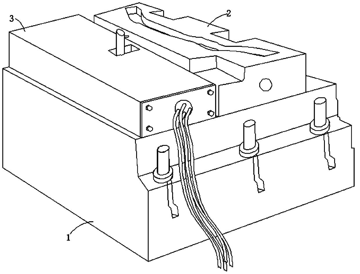
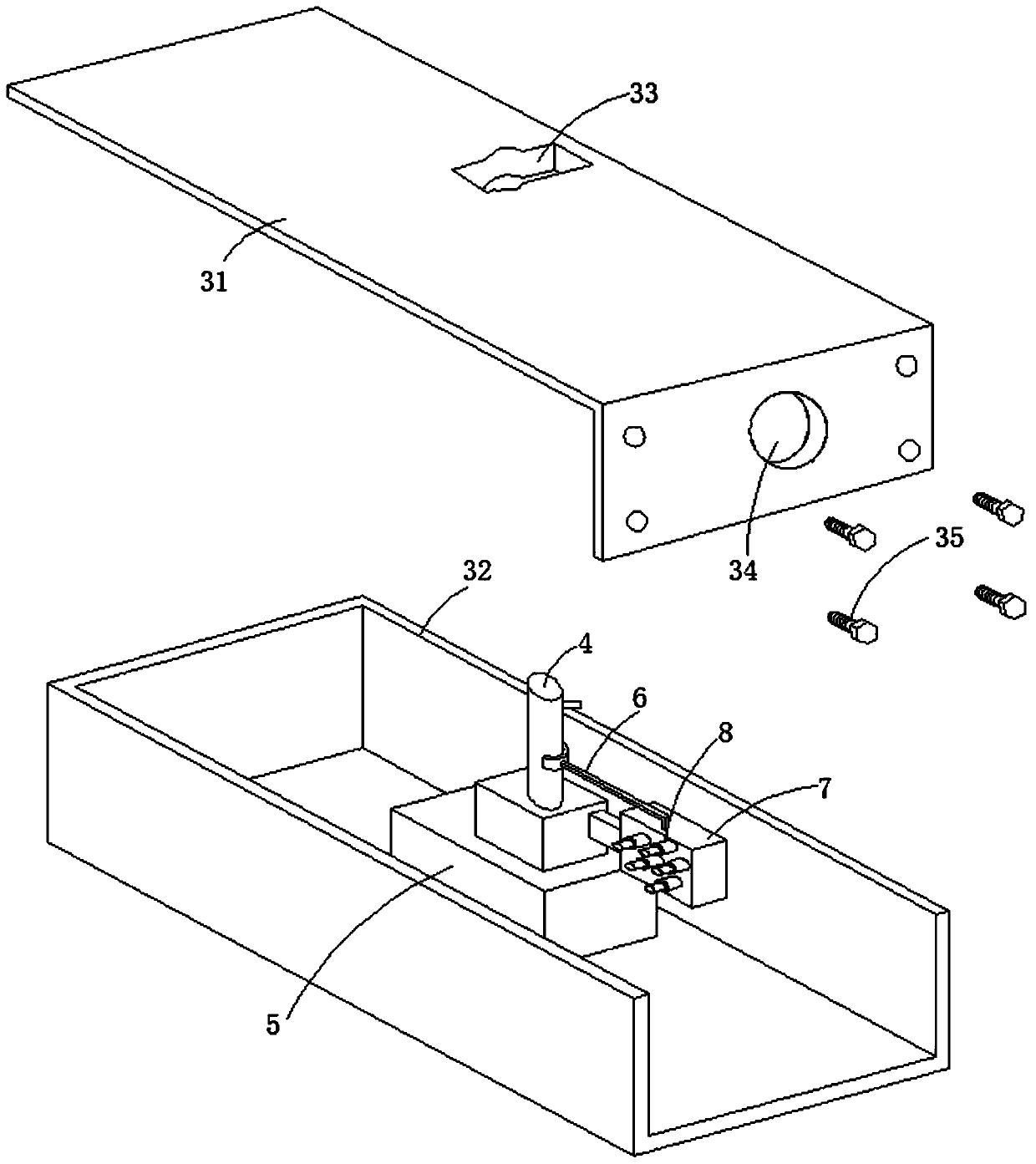
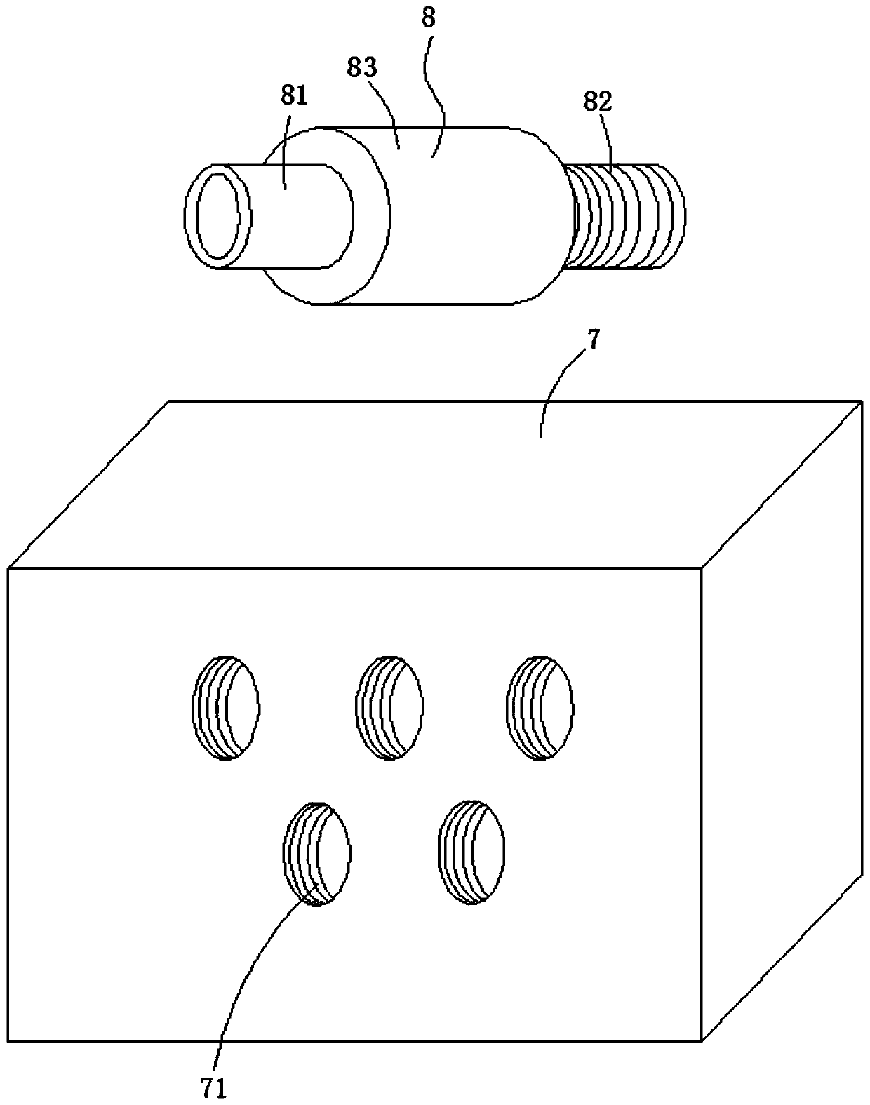
[0031] Such as Figure 1-5 As shown, a sealing structure for friction press spraying equipment is proposed in this embodiment, including a base 1, a template 2 and a spraying device 3, the template 2 and the spraying device 3 are all arranged on the base 1, and the spraying device 3 includes the installation box cover 31 and the installation box body 32, the installation box cover 31 covers the installation box body 32, and the installation box cover 31 and the installation box body 32 are connected by fixing screws 35, the horizontal plate of the installation box cover 31 A moving through hole 33 is opened, and a side through hole 34 is opened on the vertical plate of the installation box cover 31. The installation box body 32 is provided with a shower head 4 through the lifting mechanism 5, and the shower head 4 moves through the moving through hole 33, and the spray head 4 moves through the moving through hole 33. The shower head 4 is set through the liquid spray box 7 thro...

Embodiment 2

[0035] Such as Figure 5 As shown, the difference between embodiment 2 and embodiment 1 is that in embodiment 2, the end of the connecting threaded pipe 83 away from the fixed pipe 81 is fixedly provided with the first magnet pipe 11, and the first magnet pipe 11 is sleeved on the connecting pipe 82 Outside, the nut 13 is fixedly provided with the second magnet tube 15 towards one end of the connecting threaded pipe 83. Since the first magnet tube 11 and the second magnet tube 15 are attracted to each other, the connecting threaded pipe 83 and the nut 13 are formed When resisting extrusion, a better extrusion effect can be achieved.

Embodiment 3

[0037] Such as Figure 6 As shown, the difference between embodiment 3 and embodiment 2 and embodiment 1 is that in embodiment 3, the nut 13 is provided with a first moving hole 14 on the inner tube facing the side where the threaded pipe 83 is connected, and the second magnet tube 15 The inner tube is provided with a second moving hole 16, and the second moving hole 16 is connected with the first moving hole 14 to form a complete extrusion hole, and the diameter of the end of the extrusion hole close to the connecting threaded pipe 83 is larger than that of the end far away from the connecting threaded pipe 83 The hole diameter of the extrusion hole is larger on the left and smaller on the right, which can ensure that the sealing rubber tube 12 can effectively enter the extrusion hole, so that the sealing rubber tube 12 will not interfere with the movement of the nut 13 to form wrinkles, and the formation of wrinkles It will increase the probability of oil leakage. In this em...


PUM


Abstract

The invention relates to a sealing structure for spraying equipment of a friction press. The sealing structure aims at solving the problem of liquid leakage caused by poor sealing effect of a sprayingliquid conveying pipeline during spraying operation of an existing friction press. According to the sealing structure, nuts are arranged outside sealing threaded pipes in a threaded mode, the sealingthreaded pipes and spraying liquid inlet pipes are arranged in a thread mode, each spraying liquid inlet pipe consists of a fixing pipe body, a connecting pipe body and a connecting threaded pipe body, the fixing pipe bodies communicate with an external liquid pipe, the spraying liquid inlet pipes are sleeved with sealing rubber pipes, the sealing rubber pipes are fixedly arranged on the fixing pipe bodies, the free ends of the sealing rubber pipes sleeve the outer sides of the sealing threaded pipes, and the sealing rubber pipes extrude the connecting threaded pipe bodies in an abutting modethrough the nuts. The sealing structure has the advantages that the occurrence of the situation of liquid leakage in the spraying process in traditional techniques can be effectively avoided, so thatthe effect of solving resource problems can be achieved through leakage removal treatment, meanwhile, by means of leakage prevention of spraying liquid, a clean and comfortable working environment can be provided, the structural design is reasonable, and the leakage prevention effect can be effectively achieved.

Description

technical field [0001] The invention relates to the technical field of forging production equipment, in particular to a sealing structure for friction press spraying equipment. Background technique [0002] Forging is a machining process. A forging is an object in which a metal is pressured to form a required shape or a suitable compression force through plastic deformation. This force is typically achieved through the use of a hammer or pressure. The forging process creates a refined grain structure and improves the physical properties of the metal. In the actual use of components, a correct design can make the particle flow in the direction of the main pressure. Forgings need to be consistent from piece to piece, free of any porosity, inclusions, or other blemishes. Components produced by this method have a high ratio of strength to weight. The advantages of forgings are stretchable length; shrinkable length, stretchable cross section; changeable length, changeable cr...

Claims


Application Information

Patent Timeline
Patent Type & Authority Applications(China)
IPC IPC(8): B21J3/00B21K29/00F16L15/04
CPCB21J3/00B21K29/00F16L15/04
Inventor 秦学枫郝根林崔巍朱腾
Owner ANHUI HEFEI AUTO FORGING
Why Eureka
Try Eureka