A Mechanical Disturbance Throat Deviation Type Pneumatic Vectoring Nozzle

A technology of vectoring nozzle and throat, applied in the field of advanced thrust vectoring nozzle, can solve the problem of large thrust loss, achieve the effect of reducing weight, shortening length and diameter, and simplifying nozzle structure

Active Publication Date: 2022-02-08
NANJING UNIV OF AERONAUTICS & ASTRONAUTICS
View PDF6 Cites 0 Cited by
  • Summary
  • Abstract
  • Description
  • Claims
  • Application Information

AI Technical Summary

Problems solved by technology

[0004] Almost all throat offset aerodynamic vectoring nozzles generate turbulence by injecting airflow at a throat, and throat offset aerodynamic vectoring nozzles can be divided into active active type and automatic type by the source of airflow. Adapt to the passive type, and the source of the active and active type to generate the thrust vector air source is mostly an external compressor, a gas cylinder or bleed air from the high-pressure parts of the aero-engine (mostly a compressor), and its characteristic is that the thrust vector angle varies with The change in pressure ratio of the nozzle is small, but the thrust loss is relatively large for the entire aero-engine; while the adaptive passive type is to set an adaptive bypass channel to guide the high-pressure airflow at the nozzle inlet (turbine outlet) position to Injection at the specified position of the nozzle, self-adaptive generation of disturbances and finally realization of thrust vectoring, which overcomes the shortcomings of the active type and has little impact on the overall thrust of the aeroengine, but with the increase of the pressure ratio of the nozzle, the vector angle decreases also more obvious

Method used


Image

  • A Mechanical Disturbance Throat Deviation Type Pneumatic Vectoring Nozzle
  • A Mechanical Disturbance Throat Deviation Type Pneumatic Vectoring Nozzle
  • A Mechanical Disturbance Throat Deviation Type Pneumatic Vectoring Nozzle

Examples


Embodiment

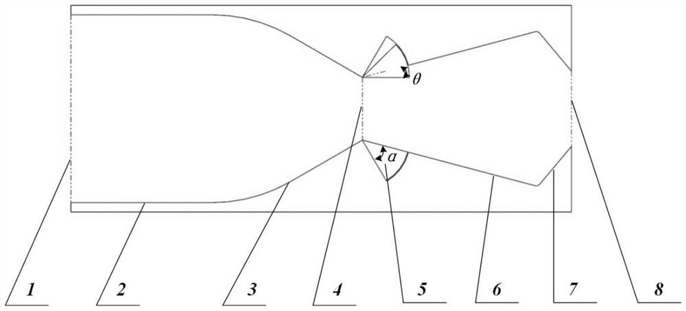
[0052] Calculations are performed for a mechanically perturbed throat-offset aerodynamic vectoring nozzle in a typical binary configuration.

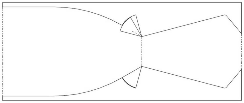
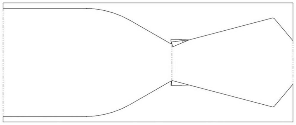
[0053] Figure 5 , 6 Shown is the numerical calculation Mach number cloud chart of NPR=2 and NPR=3 when the mechanical disturbance vane method with the rotating shaft in front of a throat sharp point and the mechanical disturbance vane is rotated out by 25%. It can be seen that, at the same degree of unscrewing, the thrust vector angle of the nozzle's working pressure ratio NPR = 2 is inclined upwards, and at this time it is the head-up vector; and when the working pressure ratio is increased to NPR = 3, the vector angle is obviously downward Oblique, the bow vector appears. This is detrimental to the aircraft control system due to the premature attachment of the airflow to the mechanical spoiler, so work at NPR ≤ 2 should be avoided for this regulation scheme.

[0054] Figure 7 Shown is the Mach number cloud diagram calculated wit...


PUM


Abstract

The invention discloses a mechanical disturbance type throat offset type pneumatic vectoring nozzle, comprising a throat offset type pneumatic vectoring nozzle body and a mechanical disturbance plate installed in the throat offset type pneumatic vectoring nozzle body, a On the one hand, a disturbance is applied near a throat through the unscrewing of the mechanical disturbance plate to generate a stable thrust vector; on the other hand, through the combined control of multiple mechanical disturbance plates, the flow adjustment of the aerodynamic vector nozzle flowing through the throat offset is realized , so that the nozzle can work efficiently in a wide range. The invention is based on the basic principle of the thrust vector generation of the throat offset type aerodynamic vector nozzle, and the disturbance generated by the action of the mechanical disturbance plate replaces the disturbance generated by the airflow injection to realize the generation of the thrust vector, and has the advantages of simple structure, light weight and wide range The adjustable internal flow rate can simultaneously have the functions of high-efficiency thrust deflection, stable thrust vector generation and flow adjustment, greatly shortening the length and diameter of the nozzle, and better meeting the needs of high-efficiency flight of the aircraft.

Description

technical field [0001] The invention relates to a mechanical disturbance type throat offset type aerodynamic vectoring nozzle, which belongs to the technical field of advanced thrust vectoring nozzles of aero-engines. Background technique [0002] With the development of science and technology and the improvement of actual demand, more and more thrust vectoring aeroengines will be used in future aircraft. The core of the thrust vectoring aeroengine to realize the thrust vectoring function is the thrust vectoring nozzle. The traditional mechanical thrust vectoring nozzle has complex structure, poor reliability and troublesome maintenance. Therefore, it is imminent to develop a thrust vectoring nozzle with simple structure, light weight and good maintainability. [0003] At present, the fluid thrust vectoring nozzle has gradually become the research focus and research focus of various countries due to its simple structure and light weight, and will enter engineering applicat...

Claims


Application Information

Patent Timeline
Patent Type & Authority Patents(China)
IPC IPC(8): F02K1/12F02K1/16F02K1/78F02K9/86F02K9/97
CPCF02K1/1207F02K1/16F02K1/002F02K1/78F02K9/86F02K9/97
Inventor 黄帅徐惊雷俞凯凯汪阳生蒋晶晶潘睿丰陈匡世宋光韬
Owner NANJING UNIV OF AERONAUTICS & ASTRONAUTICS
Why Eureka
Try Eureka