
Novel PE sealing ball valve

A kind of sealing ball valve, a new type of technology, applied in valve details, valve device, valve shell structure and other directions, can solve the problems of high precision, unstable quality, and many matching parts of the sealing ring.

Pending Publication Date: 2020-01-07
BEIJING JINGRAN LINGYUN GAS EQUIP CORP
View PDF0 Cites 3 Cited by
  • Summary
  • Abstract
  • Description
  • Claims
  • Application Information

AI Technical Summary

Problems solved by technology

[0003] Now polyethylene valves are more and more used in drinking water pipelines due to the advantages of life and price. At present, the existing problems are that the structure is complex, the sealing ring has many matching parts, the process of sub-parts requires high precision, and the cumulative error is large. The difference between each valve is large and the quality is not stable enough
At present, the complaints about polyethylene valves in the market are still concentrated on the internal leakage of the valve, most of which are due to the aging of the sealing ring under long-term compression conditions and the failure to rebound normally, resulting in internal leakage of the valve
[0004] In summary, there are obviously inconveniences and defects in the actual use of the existing technology, so it is necessary to improve

Method used

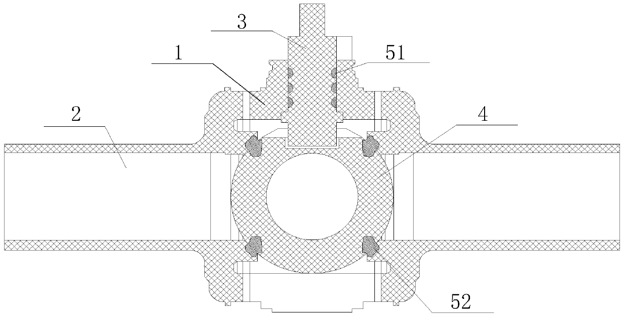
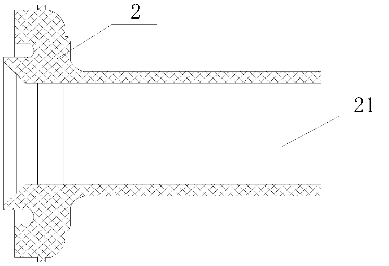
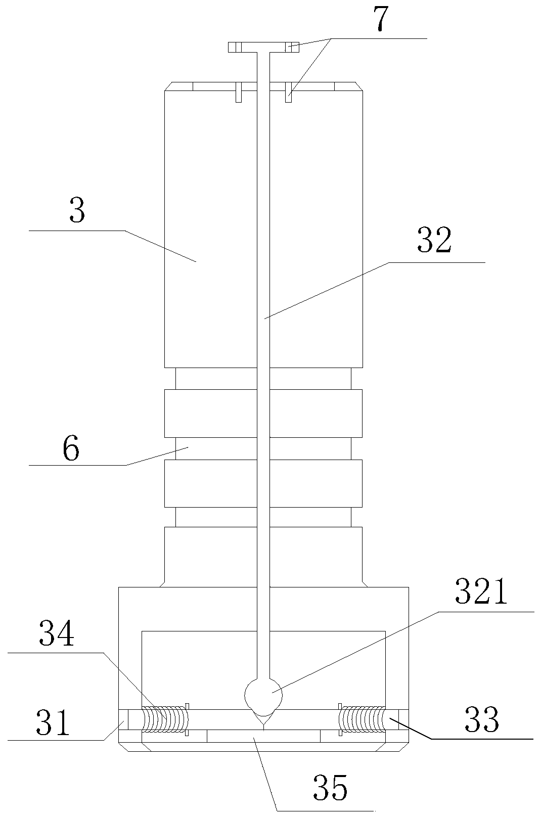

Image

  • Novel PE sealing ball valve
  • Novel PE sealing ball valve
  • Novel PE sealing ball valve

Examples


Embodiment Construction

[0021] In order to make the objectives, technical solutions and advantages of the present invention clearer, the present invention will be described in further detail below in conjunction with the accompanying drawings and embodiments. It should be understood that the specific embodiments described here are only used to explain the present invention and are not intended to limit the invention.

[0022] It should be noted that, in the description of the present invention, terms such as "upper", "lower", "left", "right", "inner", "outer" and other indicated directions or positional relationships are based on the terms shown in the accompanying drawings. The direction or positional relationship shown is only for convenience of description, and does not indicate or imply that the device or element must have a specific orientation, be constructed and operated in a specific orientation, and thus should not be construed as limiting the present invention.

[0023] In addition, it shou...


PUM


Abstract

The invention is suitable for the technical field of ball valves, and provides a novel PE sealing ball valve. The novel PE sealing ball valve comprises a valve body, a variable diameter, a valve rod and a valve element; the valve body and the variable diameter are in hot melt welding; the valve element is positioned in accommodating space formed by combining the variable diameter with the valve body; a fixed hole is formed in the valve element; a groove is formed in the fixed hole; multiple first sealing rings are arranged between the valve rod and the valve body; multiple second sealing ringsare arranged between the valve element and the variable diameter; the valve rod is provided with moving space and a limiting groove; a moving rod is arranged in the moving space; matched thread holesare formed in the upper ends of the moving rod and the valve rod; the lower end of the moving rod is a spherical end; a fixed block is arranged in the limiting groove; an elastic piece is arranged between the fixed block and the valve rod; the diameter of the spherical end is larger than the length of the limiting groove; and the fixed block is matched with the groove. The novel PE sealing ball valve can be effectively opened and closed, reduces the damage of the sealing rings, guarantees the tightness thereof, and meanwhile, can effectively adjust the position of the valve rod to prevent random opening and closing thereof.

Description

technical field [0001] The invention relates to the technical field of ball valves, in particular to a novel PE sealed ball valve. Background technique [0002] In the 1970s, the United States Swan Luosim company first developed and produced polyethylene (PE) valves, which were widely used in polyethylene (PE) gas pipeline systems. In the mid-1990s, polyethylene (PE) gas pipelines were widely used in large cities and towns in my country. People gradually realized the superiority of polyethylene (PE) valves in terms of performance and price, and gradually began to use polyethylene (PE) valves to replace them. Metal valves. [0003] Now polyethylene valves are more and more used in drinking water pipelines due to the advantages of life and price. The existing problems are that the structure is complex, the sealing ring has many matching parts, the process of sub-parts requires high precision, and the cumulative error is large. As a result, the difference between each valve is...

Claims


Application Information

Patent Timeline
IPC IPC(8): F16K5/06F16K5/08F16K27/06
CPCF16K5/0647F16K5/0668F16K5/0689F16K5/08F16K27/067
Inventor 吴飞意杨景森于发冯超樊祥胜温亚超李浩崇裴大勇
Owner BEIJING JINGRAN LINGYUN GAS EQUIP CORP
Learn More