LED stroboscopic suppression method in image sensor imaging

An image sensor and imaging technology, applied in the field of image processing, can solve problems such as motion smear, and achieve the effect of improving sensitivity

Active Publication Date: 2020-01-07
思特威(上海)电子科技股份有限公司
View PDF10 Cites 6 Cited by
  • Summary
  • Abstract
  • Description
  • Claims
  • Application Information

AI Technical Summary

Problems solved by technology

Although this implementation method can improve the dynamic range of the output, the technical solution needs to expose two frames of image data, store the first frame of image data, and synthesize the second frame of image after reading. motion smear problem

Method used


Image

  • LED stroboscopic suppression method in image sensor imaging
  • LED stroboscopic suppression method in image sensor imaging
  • LED stroboscopic suppression method in image sensor imaging

Examples


Embodiment Construction

[0021] The invention solution proposed by the present invention will be described in detail below in conjunction with each accompanying drawing provided by the present invention. The dimensions, proportions, and structures of related product designs and application example circuits recorded in multiple drawings provided by the present invention are for the purpose of explanation and description, and do not provide specific invention content and application examples provided by the present invention. Program constitutes a limitation.

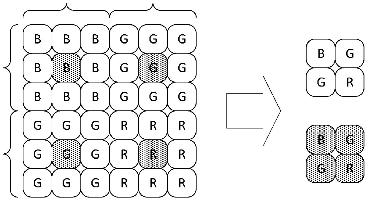
[0022] figure 2 It is a schematic diagram of the pixel unit arrangement structure in the image sensor pixel array provided by the present invention. Such as figure 2 As shown in , the pixel array of the image sensor contains several pixels arranged in rows and columns (basic pixel unit), figure 2 In the schematic diagrams given, only some pixels are listed for illustration purposes. The pixels in the pixel array of the image sensor are arr...


PUM


Abstract

The invention provides an LED stroboscopic suppression method in image sensor imaging, and the method comprises the steps: setting pixels in an image sensor pixel array as a pixel unit in a 3 * 3 structure, setting a central pixel of each pixel unit as a first group of pixels, and setting eight pixels at the periphery as a second group of pixels; wherein the first group of pixels and the second group of pixels are respectively provided with different exposure time and conversion gain, the first group of pixels is provided with longer exposure time, and the second group of pixels is provided with higher conversion gain; and the first group of pixels and the second group of pixels are exposed in one frame and are alternately output as two frames of image data line by line. The back-end processing synthesizes the two frames of images into one frame of image with a high dynamic range and outputs the image. According to the scheme provided by the invention, the flickering problem generatedby an LED signal light source when the image sensor outputs the image can be effectively inhibited, and meanwhile, the dynamic range of the image output by the image sensor can be effectively improved.

Description

technical field [0001] The invention relates to an image processing technology of an image sensor, in particular to a method for suppressing the stroboscopic problem generated by an LED light source in the application process of the image sensor and improving the output dynamic range at the same time. Background technique [0002] With the development and wide application of LED technology, traffic lights, car lights, and other identification lights used in our living environment can be commonly used in various scenarios. LED light source has various technical advantages such as small size, high luminous efficiency, good stability, and long service life, and has gradually replaced the use of traditional light sources in the field of lighting. Since the LED light source is driven by PWM (Pulse Width Modulation, Pulse Width Modulation), it generally flickers at a frequency above 90 Hz so that the human naked eye cannot recognize its switch and work normally. [0003] figure ...

Claims


Application Information

Patent Timeline
Patent Type & Authority Applications(China)
IPC IPC(8): H04N5/235
CPCH04N23/73H04N23/741
Inventor 徐辰莫要武马伟剑邵科任冠京石文杰汪小勇谢晓戚德奎
Owner 思特威(上海)电子科技股份有限公司
Why Eureka
Try Eureka