

A high branch pruning device
A pruning device and high branch technology, which is applied in the field of high branch pruning devices, can solve the problems of unfavorable appearance, uneven cross section of branches, inconvenient collection, etc., and achieve the effect of easy arrangement and appearance, convenient transportation, and convenient centralized processing
- Summary
- Abstract
- Description
- Claims
- Application Information
AI Technical Summary
Problems solved by technology
Method used
Image

Examples
specific Embodiment approach 1
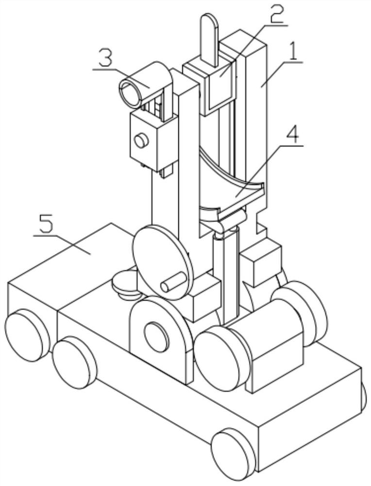
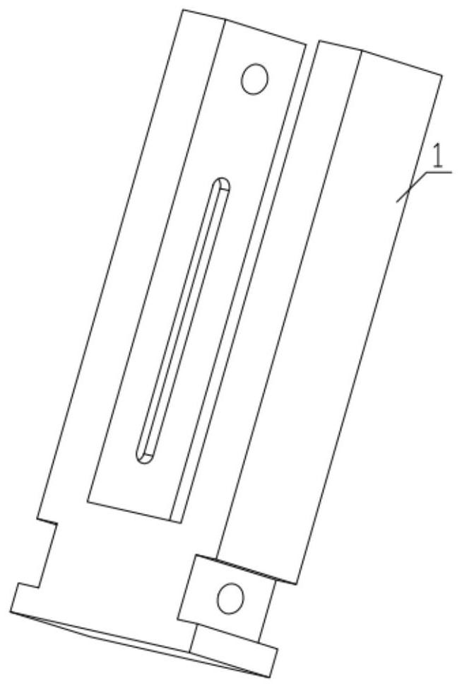
[0042] Combine below Figure 1-18Describe this embodiment, a high branch pruning device, including installation shell 1, pruning mechanism 2, auxiliary mechanism 3, rotation and collection mechanism 4 and moving mechanism 5, described pruning mechanism 2 is installed in the inner tank of installation shell 1, The auxiliary mechanism 3 is fixedly installed on one side of the installation shell 1 , one end of the rotation and collection mechanism 4 is installed on the installation casing 1 , and the other end of the rotation and collection mechanism 4 is fixedly installed on the moving mechanism 5 .
specific Embodiment approach 2
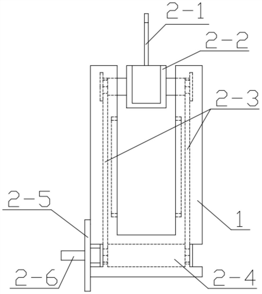
[0043] Combine below Figure 1-18 Describe this embodiment, this embodiment will further explain the first embodiment, the trimming mechanism 2 includes a chainsaw 2-1, a chainsaw frame 2-2, a gear chain 2-3, a bottom shaft 2-4, and a disc 2 -5, the handle 2-6, the chainsaw 2-1 is installed and fixed on the chainsaw frame 2-2, the number of the gear chain 2-3 has two, are respectively installed on the two ends of the chainsaw frame 2-2, simultaneously Two gear chains 2-3 are also installed on the two ends of the bottom shaft 2-4, the bottom shaft 2-4 is fixedly connected with the disc 2-5, and the disc 2-5 is fixedly connected with the handle 2-6; the chainsaw frame 2 -2 comprises U-shaped frame 2-2-1, upper end sprocket wheel 2-2-2, limit circle part 2-2-3, and the number of upper end sprocket wheel 2-2-2 has two, is respectively fixed on U At the two ends of the shape frame 2-2-1, there are two limit circle parts 2-2-3, which are respectively fixed on the two upper end spro...
specific Embodiment approach 3
[0044] Combine below Figure 1-18 Describe this embodiment, this embodiment will further explain Embodiment 1. The auxiliary mechanism 3 includes an upper half ring 3-1, a connecting clip 1 3-2, a lower half ring 3-3, and a connecting clip 2 3-4, motor 3-5, gear 3-6, connecting shell 3-7, the upper half ring 3-1 is fixed on the connecting clip 1 3-2, and the lower half ring 3-3 is fixed on the connecting clip On the second 3-4, the connecting clip one 3-2 and the connecting clip two 3-4 are all provided with gear patterns, the gear 3-6 meshes with the connecting clip two 3-4, and the gear 3-6 and the connecting clip Part one 3-2 is meshed, the gear 3-6 is fixed on the output end of the motor 3-5, the motor 3-5 is fixedly installed on the through hole connecting the shell 3-7, and the connecting clip one 3-2 is movably installed on the connection On the groove of the shell 3-7, the connecting clip two 3-4 is movably installed on the groove connecting the shell 3-7, and the mot...
PUM
 Abstract
Description
Claims
Application Information