Lifting cylinder for lifting seat

A technology for lifting and lowering air cylinders and air cylinders, which is applied to chairs, chairs, and applications that can adjust the seat vertically, can solve problems such as bursting, insufficient safety factor, and personal injury to passengers, and achieve long service life, high safety factor, and stability. Good results

Inactive Publication Date: 2020-01-10
SUZHOU XIEJIN HYDROPNEUMATIC COMPONENTS CO LTD
View PDF0 Cites 1 Cited by
  • Summary
  • Abstract
  • Description
  • Claims
  • Application Information

AI Technical Summary

Problems solved by technology

The key to a lift seat lies in its mechanism for adjusting the height of the seat plate. There are many types and forms of such height-adjusting mechanisms in the prior art; among them, the most commonly used structure is between the seat plate and the base. Set the cylinder, and then people can automatically change the height of the seat plate according to their weight after sitting on the seat plate. This type of lift seat has a greater safety hazard, and it is easy to cause the seat plate and the base to suddenly separate or even burst due to the aging of the cylinder. Then it will cause personal injury to the occupants; in addition, the height adjustment of the seat plate is realized by setting a transmission mechanism between the seat plate and the base. This type of lift seat often causes inconvenient adjustment due to the complicated structure of the transmission mechanism.
In general, the lifting seats in the prior art generally have defects such as complex structure and insufficient safety factor.

Method used


Image

  • Lifting cylinder for lifting seat

Examples


Embodiment Construction

[0014] The following will clearly and completely describe the technical solutions in the embodiments of the present invention. Obviously, the described embodiments are only some of the embodiments of the present invention, rather than all the embodiments. Based on the embodiments of the present invention, all other embodiments obtained by persons of ordinary skill in the art without making creative efforts belong to the protection scope of the present invention.

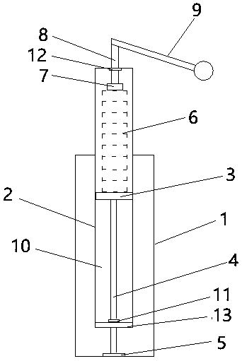
[0015] Such as figure 1 As shown, embodiments of the present invention include:

[0016] A lifting cylinder for lifting seats, comprising a cylinder block 1, a cylinder body 2, a piston 3, a piston connecting rod 4, a bearing support 5 and a spring 6, the cylinder body 2 is movably arranged in the cylinder block 1 and Extending to the upper end of the cylinder block 1, the piston connecting rod 4 is movably arranged in the cylinder block 2 and extends downward to the bottom of the cylinder block 2 to connect with th...


PUM


Abstract

The invention discloses a lifting cylinder for a lifting seat. The lifting cylinder comprises a cylinder seat, a cylinder body, a piston, a piston connecting rod, a bearing support and a spring, wherein the cylinder body is movably arranged in the cylinder seat and extends to the upper end of the cylinder seat, the piston connecting rod is movably arranged in the cylinder body and extends downwards below the cylinder body to be connected with the cylinder seat, the upper end of the piston connecting rod is movably connected with the inner wall of the cylinder body through the piston, the spring is arranged at the upper end of the piston, the lower end of the piston connecting rod is fixedly connected with the cylinder seat through the bearing support, and the cylinder body is filled with compressed gas. In this way, the lifting cylinder is suitable for being installed on the lifting seat, simple in structure and good in stability, brings convenience to adjustment of the height positionin lifting use, is long in service life, cannot explode as a result of static electricity and friction and has a high safety coefficient.

Description

technical field [0001] The invention relates to the field of lifting equipment, in particular to a lifting cylinder for lifting a seat. Background technique [0002] The lifting seat is a kind of chair for people to sit on. Its characteristic is that the height of the seat plate on the seat can be adjusted. The seat plate is slid and connected to the base along the vertical direction. The sitting height relative to the ground. The key to a lift seat lies in its mechanism for adjusting the height of the seat plate. There are many types and forms of such height-adjusting mechanisms in the prior art; among them, the most commonly used structure is between the seat plate and the base. Set the cylinder, and then people can automatically change the height of the seat plate according to their weight after sitting on the seat plate. This type of lift seat has a greater safety hazard, and it is easy to cause the seat plate and the base to suddenly separate or even burst due to the a...

Claims


Application Information

Patent Timeline
Patent Type & Authority Applications(China)
IPC IPC(8): A47C3/30F15B15/14F15B15/20F15B15/22F15B21/06
CPCA47C3/30F15B15/14F15B15/1461F15B15/20F15B15/226F15B21/06
Inventor 吴伟峰
Owner SUZHOU XIEJIN HYDROPNEUMATIC COMPONENTS CO LTD
Why Eureka
Try Eureka