
Multi-angle rotary wrench

A multi-angle, wrench technology, applied in the field of hardware, can solve the problems of the wrench being unusable, shortening the handle, affecting the labor-saving effect, etc., so as to reduce the work burden, improve work efficiency, and reduce labor intensity.

Pending Publication Date: 2020-01-10
TAIZHOU LUBA ELECTRICAL TECH CO LTD
View PDF1 Cites 0 Cited by
  • Summary
  • Abstract
  • Description
  • Claims
  • Application Information

AI Technical Summary

Benefits of technology

This new technology allows an electric motor used on vehicles to have its own pump mechanism instead of requiring manual effort from operators. It also has several technical benefits such as reduced energy consumption during high-speed operations, improved performance at low speeds, increased safety features due to enhanced control over movement, etc., resulting in better overall vehicle operational capabilities.

Problems solved by technology

This patented technical problem addressed in this patents relates to improving the functionality of conventional tools such as power saws without sacrificing their strength during operation.

Method used


Image

  • Multi-angle rotary wrench
  • Multi-angle rotary wrench
  • Multi-angle rotary wrench

Examples


Embodiment Construction

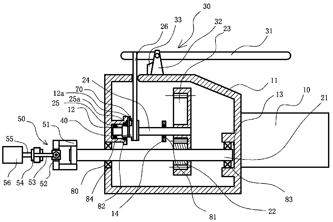
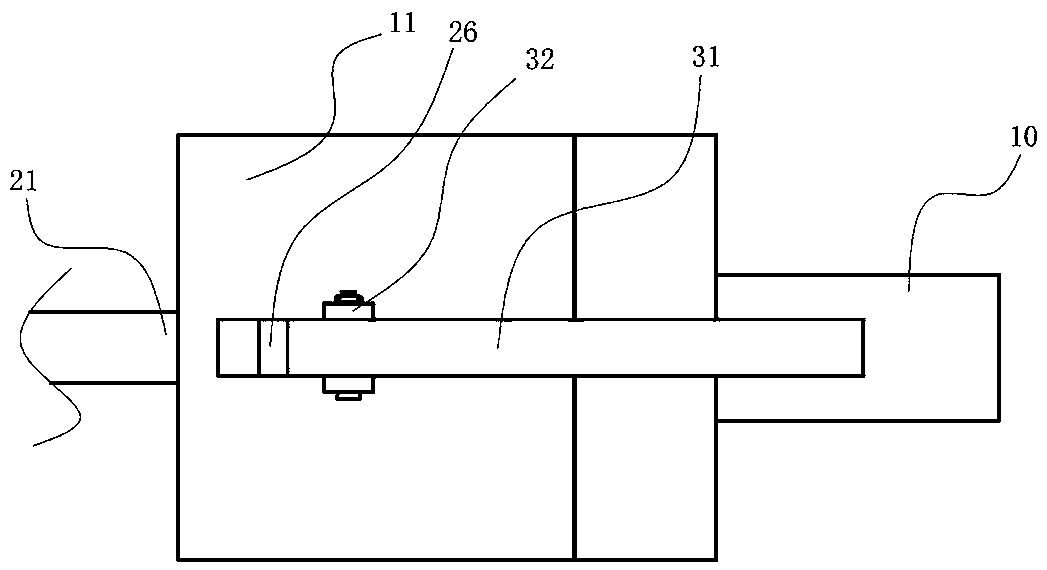
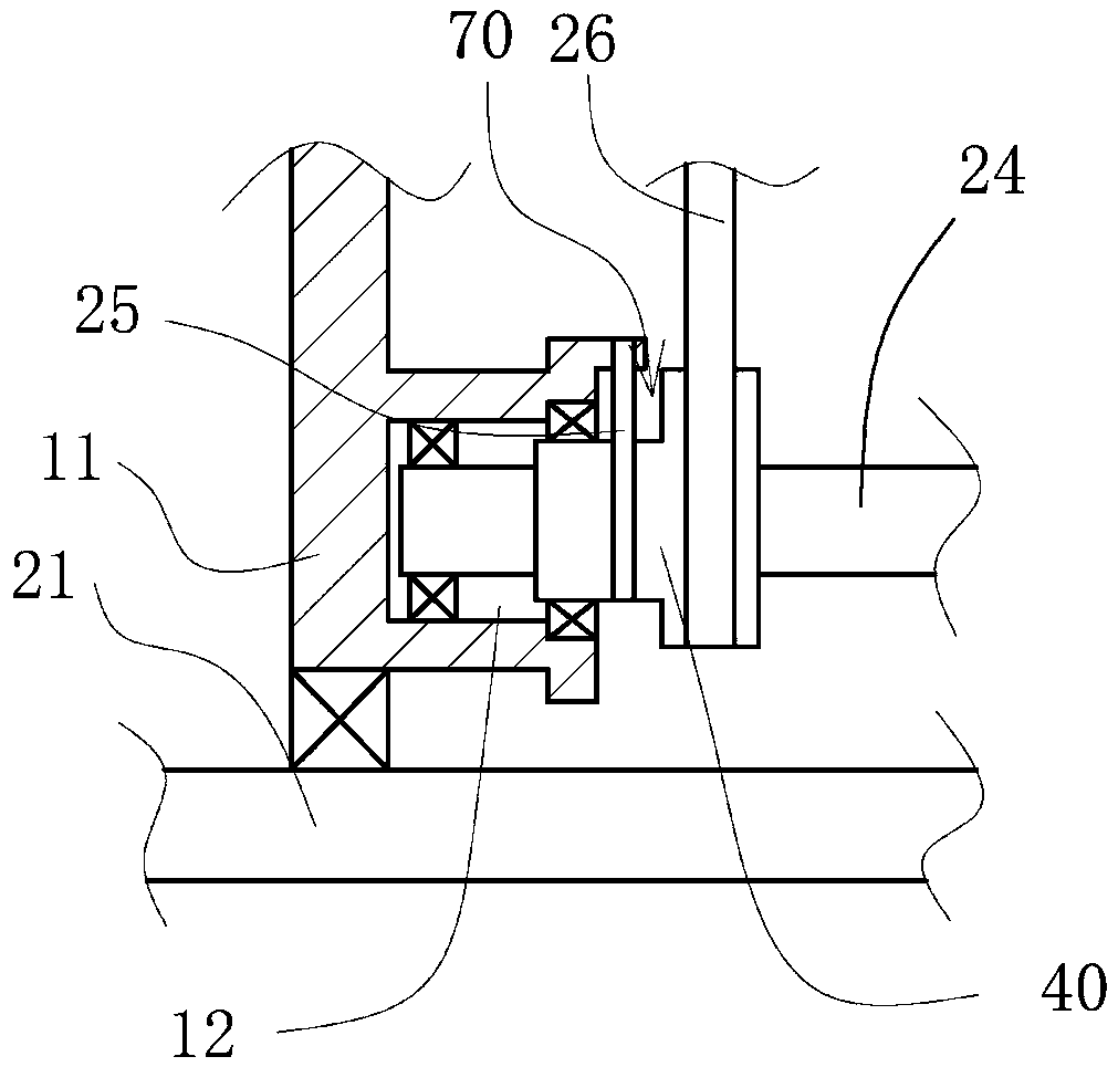
[0026] like figure 1 , figure 2 and image 3As shown, the multi-angle rotary wrench of the present invention includes a housing 11, the rear end of the housing 11 is provided with a handle 10, the front end of the inner cavity of the housing 11 is provided with a front groove 12, and the middle end of the inner cavity of the housing 11 is provided with a bearing groove 14, The center of the front groove 12 and the center of the bearing groove 14 are on the same axis, and the front groove 12 is provided with a drive shaft 24, the drive shaft 24 passes through the bearing groove 14, and one end of the drive shaft 24 is rotatably connected with the front groove 12 through a bearing one 80 , the driving shaft 24 is rotatably connected to the bearing groove 14 through the bearing 2 81, the other end of the driving shaft 24 is connected with the acceleration gear set 20, the other end of the acceleration gear set 20 is connected with the transmission shaft 21, and the rear end of ...


PUM


Abstract

The invention discloses a multi-angle rotary wrench. The wrench structurally comprises a shell, wherein an acceleration gear set is arranged in the shell, the acceleration gear set is internally connected with a driving shaft and a transmission shaft, the driving shaft is connected with a reciprocating rotating device, the reciprocating rotating device is powered through a power device on the upper part of the shell, the reciprocating rotating device completes return motion through a driving device at the front end, the front end of the transmission shaft is provided with a rotating device capable of rotating at multiple angles, and the front end of the rotating device is provided with a cover body fixed to a workpiece. The wrench has the beneficial effects that the slow rotating speed andthe small revolution number can be changed into fast rotating speed and the large revolution number, meanwhile, the power device is matched, the power to be applied is reduced, and the cover body israpidly rotated by pressing a pressing rod in a small amplitude mode.

Description


Claims


Application Information

Patent Timeline
Owner TAIZHOU LUBA ELECTRICAL TECH CO LTD
Learn More