Robot visual calibrating method based on perspective transformation model

A technology of robot vision and perspective transformation, applied in the field of robotics, can solve the problems of cumbersome calibration process, complex calibration process, and inability to meet the precision requirements of industrial robots, and achieve the effects of cost reduction, simple calibration process, and high calibration accuracy

Active Publication Date: 2020-01-10
HUAZHONG UNIV OF SCI & TECH
View PDF5 Cites 13 Cited by
  • Summary
  • Abstract
  • Description
  • Claims
  • Application Information

AI Technical Summary

Problems solved by technology

[0003] The calibration methods in the prior art have different problems and defects, mainly including: the accuracy of the active visual calibration method and the self-calibration method is not as good as the traditional calibration method, and cannot meet the accuracy requirements of the industrial field robot vision calibration; the traditional calibration method

Method used


Image

  • Robot visual calibrating method based on perspective transformation model
  • Robot visual calibrating method based on perspective transformation model
  • Robot visual calibrating method based on perspective transformation model

Examples


Embodiment

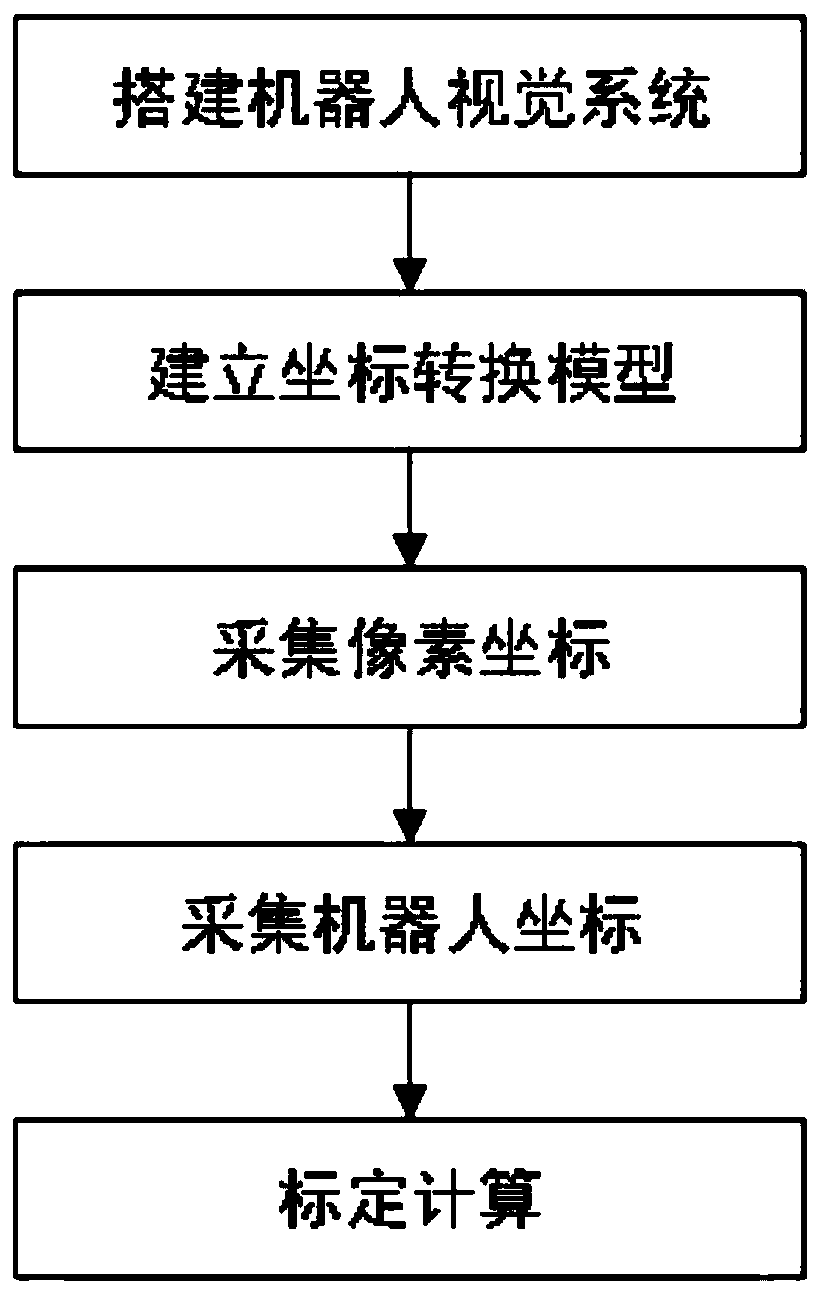
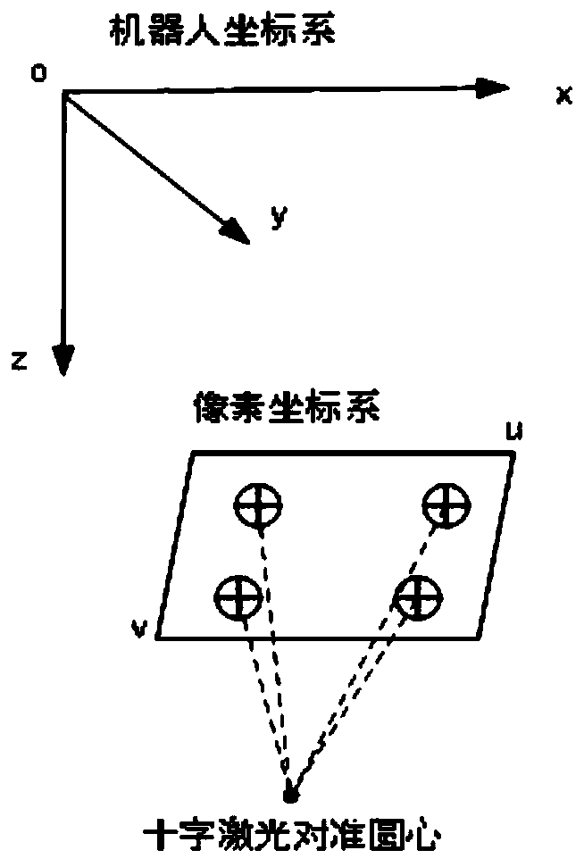
[0040] A robot vision calibration method based on a perspective transformation model. According to the perspective transformation principle between plane coordinate systems, the relationship between the pixel coordinate system and the robot coordinate system is established, and four sets of pixel coordinates and coordinates are collected by using four non-collinear mark points. Robot coordinates, calibration and calculation of coordinate transformation model parameters, used for vision-guided robot positioning. Process such as figure 1 As shown, it specifically includes the following steps:

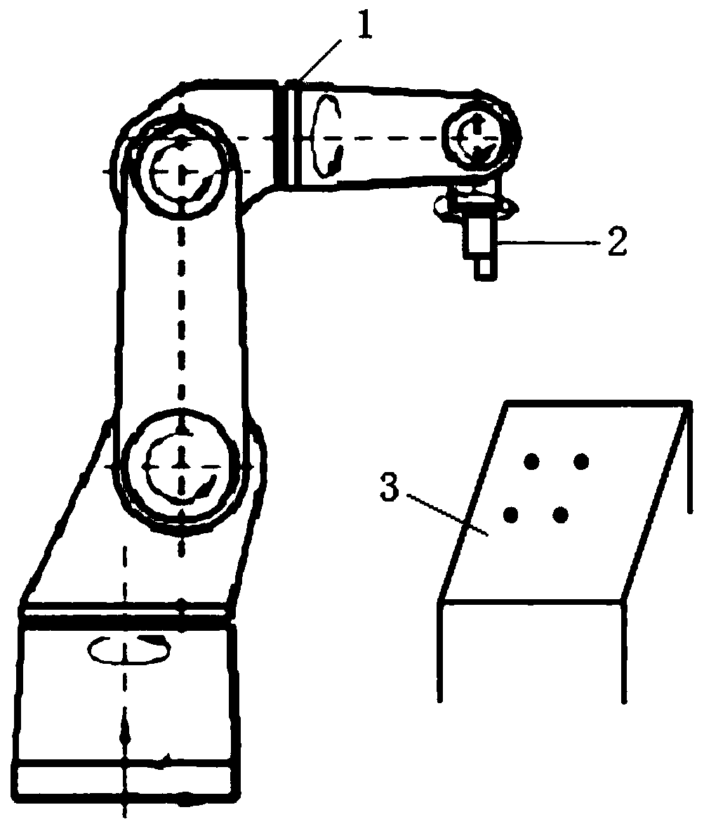
[0041] S1: Build a robot vision system. Taking the terminal camera as an example, the robot vision system such as figure 2 As shown, a camera 2 is installed at the end of the industrial six-axis robot 1, and the camera 2 moves with the end of the robot 1. The camera shoots downwards, and keeps the height constant when taking pictures; the height of the picture can be determined by the ...


PUM


Abstract

The invention discloses a robot visual calibrating method based on a perspective transformation model. The relation between a pixel coordinate system and a robot coordinate system is built according to a perspective transformation principle between plane coordinate systems; and four sets of pixel coordinates and robot coordinates are acquired by using four non-collinear marking points to calibrateand calculate coordinate conversion model parameters for visual guide robot positioning. The method can be used for calibrating fixed cameras or terminal cameras mounted on robots without consideringthe depth direction, and is low in cost, high in calibrating precision and suitable for visual positioning requirements of industrial scene robots.

Description

technical field [0001] The invention belongs to the technical field of robots and relates to visual calibration technology, in particular to a robot visual calibration method based on a perspective transformation model. Background technique [0002] With the continuous development of science and technology, the use of robots is becoming more and more frequent, and more and more industrial fields are beginning to use robots to replace manual work, such as using machine vision to replace traditional detection, measurement, identification and positioning guidance that require human eyes and other repetitive work. In vision applications, such as measurement and positioning, vision calibration is essential. Existing calibration methods can be roughly divided into three categories: traditional calibration methods, active vision calibration methods and self-calibration methods. [0003] The calibration methods in the prior art have different problems and defects, mainly including:...

Claims


Application Information

Patent Timeline
IPC IPC(8): B25J9/16
CPCB25J9/1653
Inventor 宋宝唐小琦李含嫣周向东叶亚红肖千红刘永兴徐迪炜李鹏帅
Owner HUAZHONG UNIV OF SCI & TECH
Why Eureka
Try Eureka