
Elevator gap inspection device

An inspection device and gap technology, applied in transportation and packaging, mechanical gap measurement, elevators, etc., can solve the problems of occupied space, tedious time-consuming, cumbersome, etc., to reduce the occupied space, improve the convenience of use, quick disassembly and maintenance. The effect of assembly

Pending Publication Date: 2020-01-10
山东省特种设备检验研究院枣庄分院
View PDF0 Cites 6 Cited by
  • Summary
  • Abstract
  • Description
  • Claims
  • Application Information

AI Technical Summary

Problems solved by technology

[0002] The measurement of the elevator door gap and floor and car door sill dimensions is an important inspection item in the elevator inspection process, but it is also the most cumbersome item. Not only the measurement data is large, Moreover, because most of the detection parts are in narrow spaces, it is difficult to read data, resulting in low inspection and detection efficiency
[0003] At present, with the development of elevator inspection equipment, people mostly use a kind of elevator gap inspection device to quickly measure these gaps, but most of the inspection steps set by the existing elevator gap inspection device are fixed and occupy a lot of space when carrying. The space position affects the movement and carrying of the inspection device, and it is not convenient for the maintenance of the inspection device in the later stage. Moreover, when the handle bar of the existing elevator gap inspection device is adjusted to the angle position, it is mostly fixed by screws, which is cumbersome and time-consuming. Reduced the convenience of use of the inspection device

Method used


Image

  • Elevator gap inspection device
  • Elevator gap inspection device
  • Elevator gap inspection device

Examples


Embodiment Construction

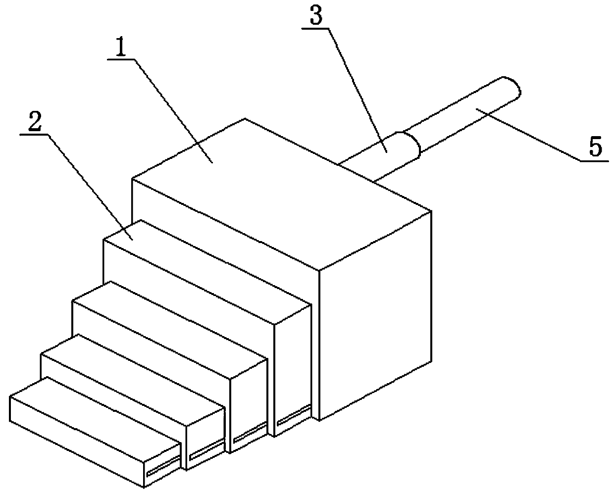
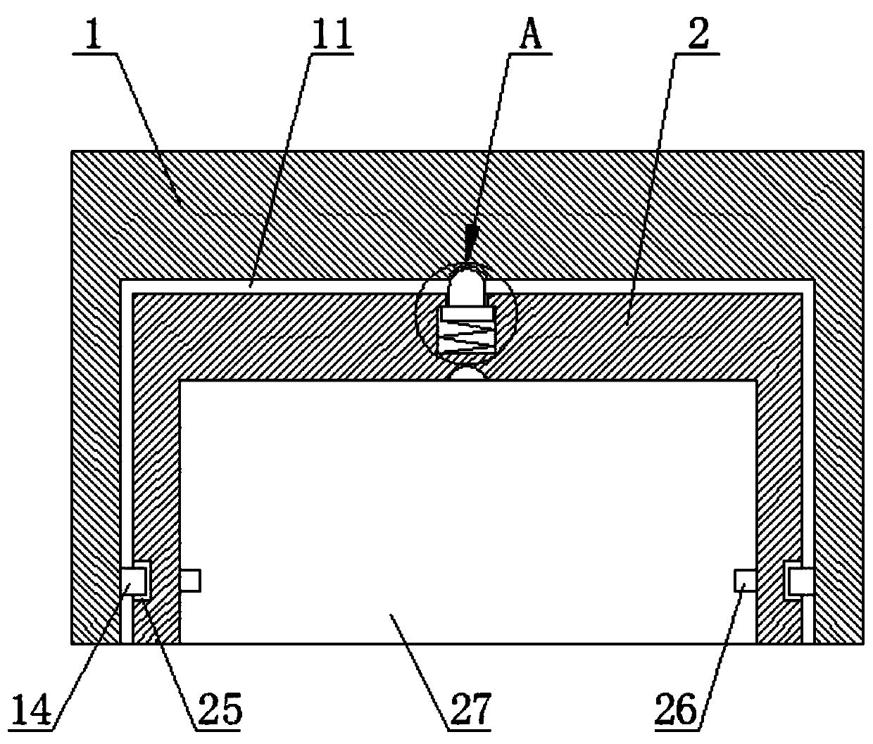
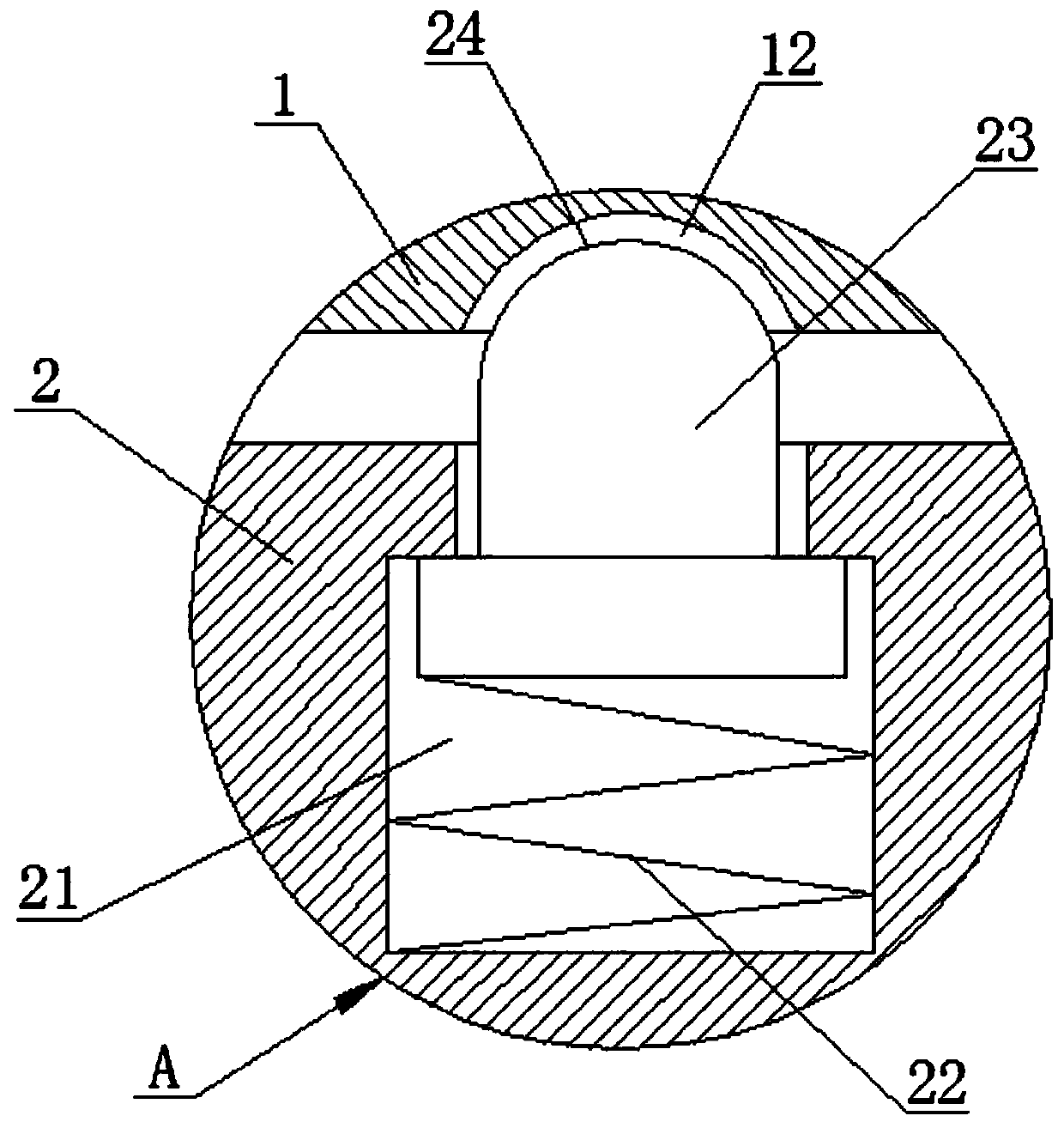
[0029] The following will clearly and completely describe the technical solutions in the embodiments of the present invention with reference to the accompanying drawings in the embodiments of the present invention. Obviously, the described embodiments are only some, not all, embodiments of the present invention. Based on the embodiments of the present invention, all other embodiments obtained by persons of ordinary skill in the art without making creative efforts belong to the protection scope of the present invention.

[0030] see Figure 1-6 , a kind of elevator gap inspection device, comprises inspection block main body 1, please refer to Figure 1-6 The left side of the inspection block main body 1 is provided with a first avoidance groove 11, and the upper inner wall of the first avoidance groove 11 is respectively provided with a front clamping hole 12 and a rear clamping hole 13, and the front clamping hole 12 is used to fix the inspection step 2. The protruding positi...


PUM


Abstract

The invention discloses an elevator gap inspection device, and belongs to the technical field of elevator inspection devices. The left side of an inspection block body is provided with a first clearance groove, the inner wall of the upper end of the first clearance groove is provided with a front clamping hole and a back clamping hole, inspection steps are slidably connected to the interior of thefirst clearance groove, the upper end of the inspection steps is provided with a groove, a first spring is connected to the interior of the groove in a contact manner, the upper end of the first spring is in contact connection with a clamping rod, the clamping rod is provided with a circular arc end, and the upper end of the clamping rod is connected with the front clamping hole in a clamping manner. According to the elevator gap inspection device, the arranged inspection steps with different heights have a telescoping function, an arranged handle rod also has a telescopic folding function, therefore, the occupation space position of the inspection device can be decreased, and the inspection device can be greatly conveniently moved and carried; the arranged inspection steps and handle rodhave an automatic positioning function, and the using convenience of the inspection device is improved; and in addition, the inspection steps can be quickly disassembled and assembled, and later maintenance of the inspection device is convenient.

Description

technical field [0001] The present invention relates to the technical field of elevator detection devices, and more specifically, to an elevator gap inspection device. Background technique [0002] The measurement of the elevator door leaf gap and floor and car door sill dimensions is an important inspection item in the elevator inspection process, but it is also the most cumbersome item. The detection efficiency is low. [0003] At present, with the development of elevator inspection equipment, people mostly use a kind of elevator gap inspection device to quickly measure these gaps, but most of the inspection steps set by the existing elevator gap inspection device are fixed and occupy a lot of space when carrying. The space position affects the movement and carrying of the inspection device, and it is not convenient for the maintenance of the inspection device in the later stage. Moreover, when the handle bar of the existing elevator gap inspection device is adjusted to t...

Claims


Application Information

Patent Timeline
IPC IPC(8): B66B5/00G01B5/14
CPCB66B5/0037G01B5/14
Inventor 扈然
Owner 山东省特种设备检验研究院枣庄分院
Learn More