
Aluminum template vertical conveyor

A transporter and aluminum mold technology, which is applied in the direction of lifting equipment safety device, lifting device, and lifting frame, etc., can solve the problems of falling down of the transfer box, failure of electronic self-locking, and low safety of aluminum template transportation, etc. Transport safety, flexible locking effect

Inactive Publication Date: 2020-01-10
GUANGDONG BOZHILIN ROBOT CO LTD
View PDF7 Cites 3 Cited by
  • Summary
  • Abstract
  • Description
  • Claims
  • Application Information

AI Technical Summary

Problems solved by technology

[0002] The full name of aluminum formwork is aluminum alloy formwork for construction. It is a new generation of formwork system after wood formwork and steel formwork. It can be freely combined according to different structural sizes. The design, development and construction application of aluminum formwork is a major development process in the construction industry. , in construction applications, when the aluminum formwork is transported from the lower floor to the upper floor, it is usually transported by an aluminum formwork vertical conveyor. During the transmission process, the transport mechanism drives the movement of the material transfer box used to load the aluminum formwork, and then conveys the aluminum formwork. Existing The electronic self-locking function of the aluminum mold vertical conveyor prevents the material transfer box from falling backwards, but the electronic self-locking function is not completely reliable. In the case of a sudden power failure or a wrong program, the electronic self-locking has the risk of failure, resulting in There is a risk of the material transfer box falling downwards, which makes the transportation safety of the aluminum formwork not high

Method used


Image

  • Aluminum template vertical conveyor
  • Aluminum template vertical conveyor
  • Aluminum template vertical conveyor

Examples


Embodiment Construction

[0037] The following will clearly and completely describe the technical solutions of the embodiments of the present application with reference to the accompanying drawings. Apparently, the described embodiments are part of the embodiments of the present application, not all of them. Based on the embodiments in the embodiments of the present application, all other embodiments obtained by persons of ordinary skill in the art without making creative efforts belong to the protection scope of the embodiments of the present application.

[0038] In the description of the embodiments of the present application, it should be noted that the terms "center", "upper", "lower", "left", "right", "vertical", "horizontal", "inner", "outer " and other indicated orientations or positional relationships are based on the orientations or positional relationships shown in the drawings, and are only for the convenience of describing the embodiments of the present application and simplifying the descr...


PUM


Abstract

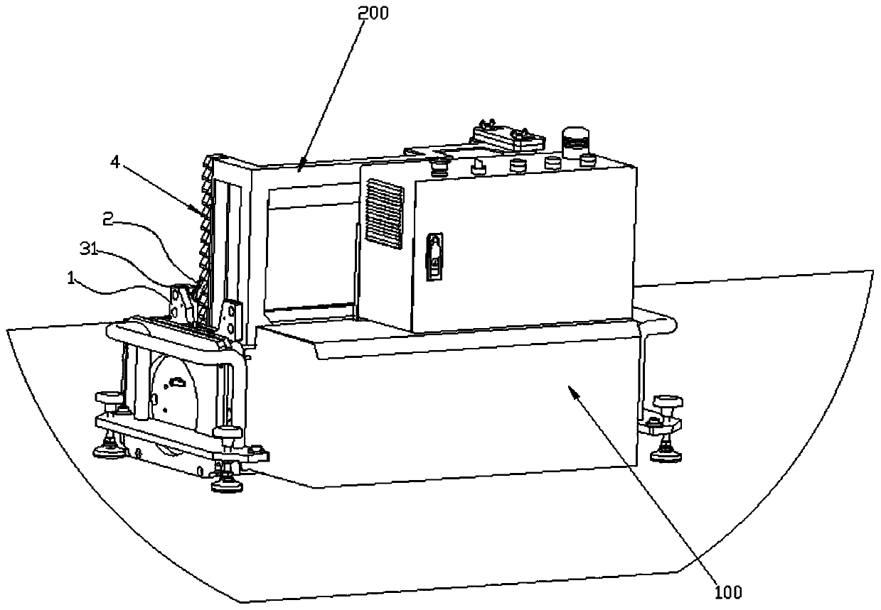
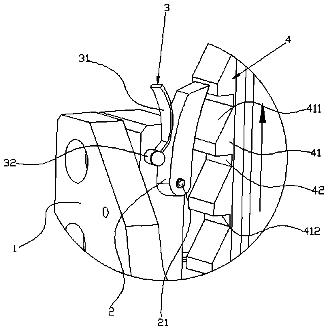
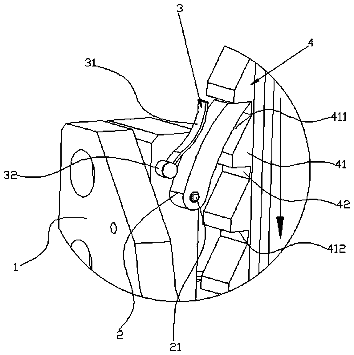
The invention discloses an aluminum template vertical conveyor. A main machine body, a driver and a material conveying box are included. The material conveying box and the main machine body are in sliding fit. The driver is arranged on the main machine body and used for driving the material conveying box to move. An anti-falling mechanism is further included and comprises a fixing base, a clamp block, an elastic piece and a rack, wherein the fixing base is arranged on the main machine body, the clamp block is arranged on the fixing base, and the elastic piece is arranged on the fixing base andused for tightly abutting against the clamp block so that the clamp block can be movably clamped in a tooth groove in the rack. The rack is arranged on the material conveying box, and teeth on the rack are provided with extrusion faces and locking faces, wherein when the material conveying box does the ascending movement, the extrusion faces are in sliding fit with the clamp block and are used for extruding the clamp block out of the tooth groove, and when the material conveying box does the descending movement, the locking faces abut against the clamp block in a locking manner. When the material conveying box falls due to the conveyor electronic self-lock failure situation, the clamp block can be in mechanical locking fit with the rack, accordingly, falling of the material conveying boxis stopped, and aluminum template transportation safety is improved.

Description

technical field [0001] The present application relates to the technical field of aluminum mold transportation, in particular to an aluminum mold vertical conveyor. Background technique [0002] The full name of aluminum formwork is aluminum alloy formwork for construction. It is a new generation of formwork system after wood formwork and steel formwork. It can be freely combined according to different structural sizes. The design, development and construction application of aluminum formwork is a major development process in the construction industry. , in construction applications, when the aluminum formwork is transported from the lower floor to the upper floor, it is usually transported by an aluminum formwork vertical conveyor. During the transmission process, the transport mechanism drives the movement of the material transfer box used to load the aluminum formwork, and then conveys the aluminum formwork. Existing The electronic self-locking function of the aluminum mol...

Claims


Application Information

Patent Timeline
Patent Type & Authority Applications(China)
IPC IPC(8): B66F7/28B66F17/00
CPCB66F7/28B66F17/00
Inventor 陈浩李昂郑丰潘克玉谢志锋陈伯扦
Owner GUANGDONG BOZHILIN ROBOT CO LTD
Learn More