
A performance testing device for low-dimensional optoelectronic materials

A technology for optoelectronic materials and testing devices, which is used in measuring devices, material analysis by optical means, and material analysis, etc., which can solve problems such as inaccurate results and changes in the area where the light intensity cannot be illuminated.

Active Publication Date: 2021-12-24
ZHENGZHOU UNIVERSITY OF AERONAUTICS
View PDF0 Cites 1 Cited by
  • Summary
  • Abstract
  • Description
  • Claims
  • Application Information

AI Technical Summary

Problems solved by technology

[0006] In view of the above situation, in order to overcome the defects of the prior art, the present invention provides a performance testing device for low-dimensional photoelectric materials, which effectively solves the problem of inaccurate results when using artificial light sources for testing, and at the same time solves the problem of inability to test the The problem of changing the intensity of light on the structure to be tested and the area of ​​light

Method used


Image

  • A performance testing device for low-dimensional optoelectronic materials
  • A performance testing device for low-dimensional optoelectronic materials
  • A performance testing device for low-dimensional optoelectronic materials

Examples


Embodiment 1

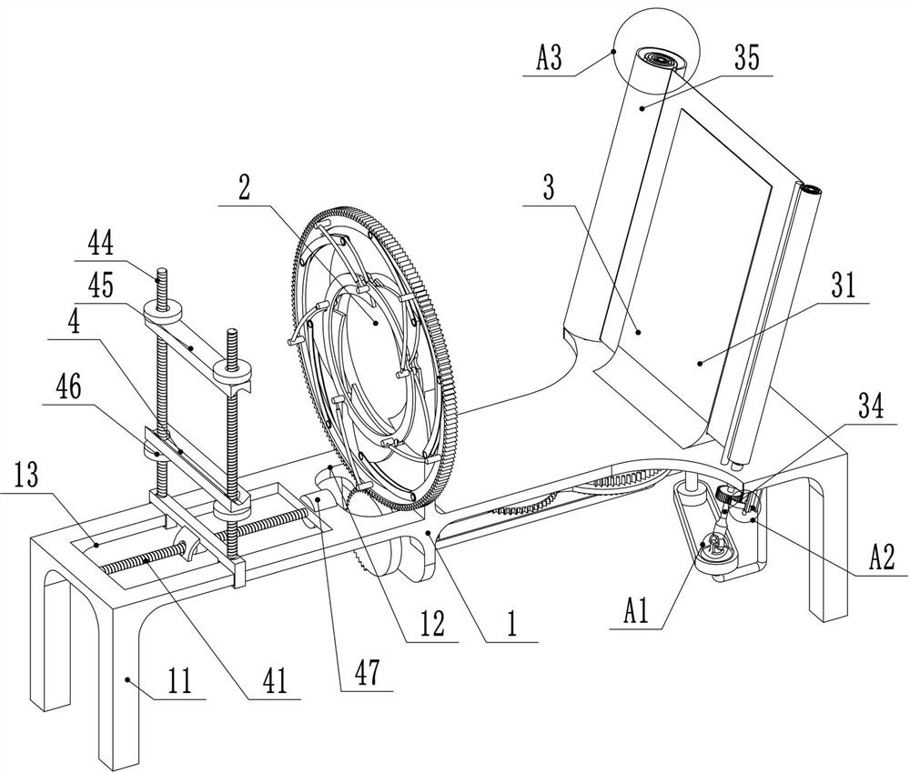
[0042] Embodiment 1, the present invention is a performance testing device for low-dimensional photoelectric materials, including a bracket 1, a light-concentrating structure 2 is installed in the middle of the bracket 1, a light-reflecting structure 3 is installed at one end of the bracket 1, and the other end of the bracket 1 The fixed structure 4 of the device to be detected is installed, and the bottom end of the bracket 1 is equipped with a power structure 5. The power structure 5 is connected to the first transmission structure 6, and the first transmission structure 6 is respectively connected to the light-concentrating structure 2 and the light-reflecting structure 3 through the transfer transmission structure. connection, the transfer transmission structure includes a second transmission structure 7 and a third transmission structure 8, the first transmission structure 6 is connected to the reflective structure 3 through the second transmission structure 7, and the firs...

Embodiment 2

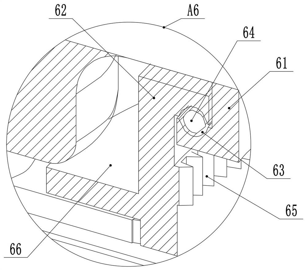
[0043] Embodiment 2. On the basis of Embodiment 1, the light-concentrating structure 2 includes an inner ring 21 and an outer gear ring 26. The inner ring 21 is installed on the surface of the bracket 1. A convex lens 22 is installed inside one side of the inner ring 21. The inner ring 21 The other side of 21 is provided with a chute 23 inside, and the inside of the chute 23 is rotatably connected with a baffle plate 24. The side of the baffle plate 24 is connected with the outer gear ring 26 through an arc-shaped connecting plate 25, and the connection between the outer gear ring 26 and the inner ring 21 There is also a piston tube 27 connected between them, the external gear ring 26 is meshed with a toggle gear 89, an opening 12 is opened at the position corresponding to the toggle gear 89 on the bracket 1, and the toggle gear 89 is set to 1 / 2 teeth. The structural setting of the shaped connecting plate 25 makes the position of the rear baffle plate 24 change when the toggle ...

Embodiment 3

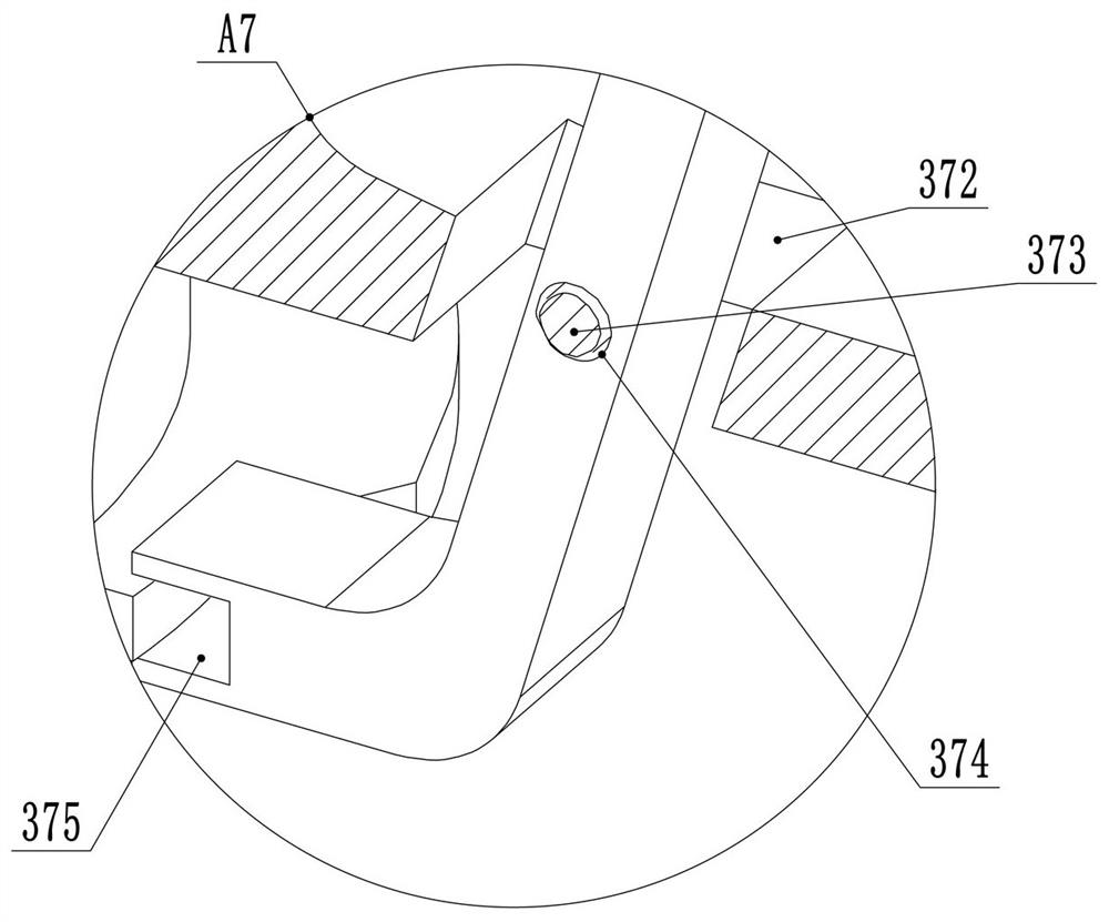
[0044] Embodiment 3, on the basis of Embodiment 1, the reflective structure 3 includes a high-transparency glass plate 31 obliquely installed on the surface of the bracket 1, the reflective area of ​​the high-transparency glass plate 31 is larger than the light-transmitting area of ​​the light-condensing structure 2, and the high-transparency The inside of the glass plate 31 is provided with a slide groove 32, the inside of the slide groove 32 is slidably connected with a reflective film 33, one end of the reflective film 33 is connected with a reflective film collecting shaft 34, and the other end of the reflective film 33 is connected with a reflective film installation pipe 35. The pressing frame 36 that presses the reflective film 33 is installed on the surface of the transparent glass plate 31 far away from the concentrating structure 2, and a pressing plate 37 is installed at the position corresponding to the pressing frame 36 on the support 1; the pressing frame 36 is pus...


PUM


Abstract

The invention relates to the technical field of testing low-dimensional photoelectric materials, in particular to a performance testing device for low-dimensional photoelectric materials, which effectively solves the problem of inaccurate test results when artificial light sources are used, and at the same time solves the problem of not being able to irradiate the surface to be tested. The problem of changing the intensity of light on the structure and the area of ​​light; the technical solution includes a bracket, a light-concentrating structure is installed in the middle of the bracket, a reflective structure is installed at one end of the bracket, and a fixing structure for the device to be detected is installed at the other end of the bracket. The bottom end of the bracket is equipped with a power structure, and the power structure is connected with a first transmission structure. The first transmission structure is respectively connected to the light-concentrating structure and the light-reflecting structure through the relay transmission structure. The relay transmission structure includes the second transmission structure and the third transmission structure. , the first transmission structure is connected to the reflective structure through the second transmission structure, and the first transmission structure is connected to the light concentrating structure through the third transmission structure.

Description

technical field [0001] The invention relates to the technical field of testing low-dimensional photoelectric materials, in particular to a performance testing device for low-dimensional photoelectric materials. Background technique [0002] Low-dimensional optoelectronic materials are new functional materials that have been developed rapidly in the world in the past ten years. Effect, so that low-dimensional optoelectronic materials exhibit excellent electrical transport and photoelectric conversion properties different from bulk materials, and have important application potential in the development of future high-performance optoelectronic information devices, new green energy, biomedicine and other fields . [0003] Before low-dimensional photoelectric materials are put into practical use, it is often necessary to test various properties of the material. The properties that are often tested mainly include micro-torsion mechanical performance testing, bending fatigue relia...

Claims


Application Information

Patent Timeline
Patent Type & Authority Patents(China)
IPC IPC(8): G01N21/63G01N21/01
CPCG01N21/63G01N21/01G01N2021/0112
Inventor 杜银霄段向阳许晓丽邵立陈灿侯海兴
Owner ZHENGZHOU UNIVERSITY OF AERONAUTICS
Learn More