Ultrasonic coaxial assisted dual-shaft-shoulder friction stir welding method

A friction stir welding and friction stir technology, which is applied in welding equipment, non-electric welding equipment, metal processing equipment, etc., can solve the problems of affecting the strength of joints, large heat affected zone of the weld, and reducing the service life of the stirring head. The effect of utilization

Inactive Publication Date: 2020-01-14
JIANGSU UNIV OF TECH
View PDF8 Cites 6 Cited by
  • Summary
  • Abstract
  • Description
  • Claims
  • Application Information

AI Technical Summary

Problems solved by technology

[0006] In order to solve the problem that the heat input of double-shaft shoulder friction stir welding is relatively high in the prior art, the heat-affected zone of the weld seam is relatively large, which affects the strength of the joint; The invention provides an ultrasonic coaxial assisted dual shoulder friction stir welding method, which improves the utilization rate of ultrasonic energy by applying coaxial ultrasonic vibration to the bottom of the lower shoulder of the dual shoulder friction stir welding head
Ultrasonic energy can be transmitted to the plastic deformation zone around the stirring needle through the lower shaft shoulder and the stirring needle, reducing the yield strength of the material and increasing the plastic fluidity of the material, so as to solve welding defects such as unwelded and holes at low speed, thereby reducing welding heat input, to ensure the quality of welded joints and extend the life of the stirring head at the same time

Method used


Image

  • Ultrasonic coaxial assisted dual-shaft-shoulder friction stir welding method
  • Ultrasonic coaxial assisted dual-shaft-shoulder friction stir welding method
  • Ultrasonic coaxial assisted dual-shaft-shoulder friction stir welding method

Examples


Embodiment 1

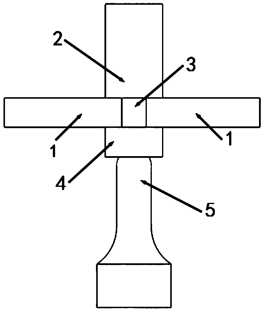
[0028] combine figure 1 , a method for ultrasonic coaxially assisted double-shoulder friction stir welding, comprising the following steps:

[0029] (1) The workpiece 1 to be welded is placed on the welding platform in the form of butt joint, and the two are clamped and fixed with a tooling fixture to ensure that the two do not move staggered during the welding process.

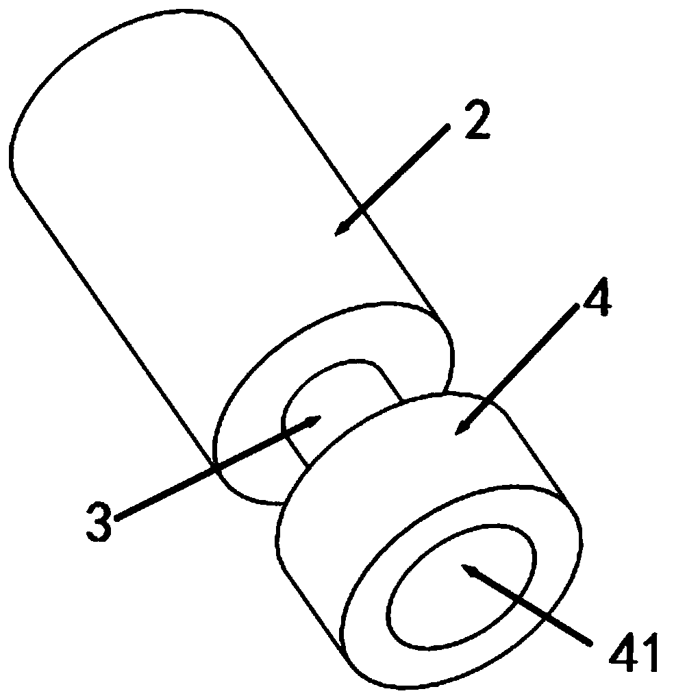
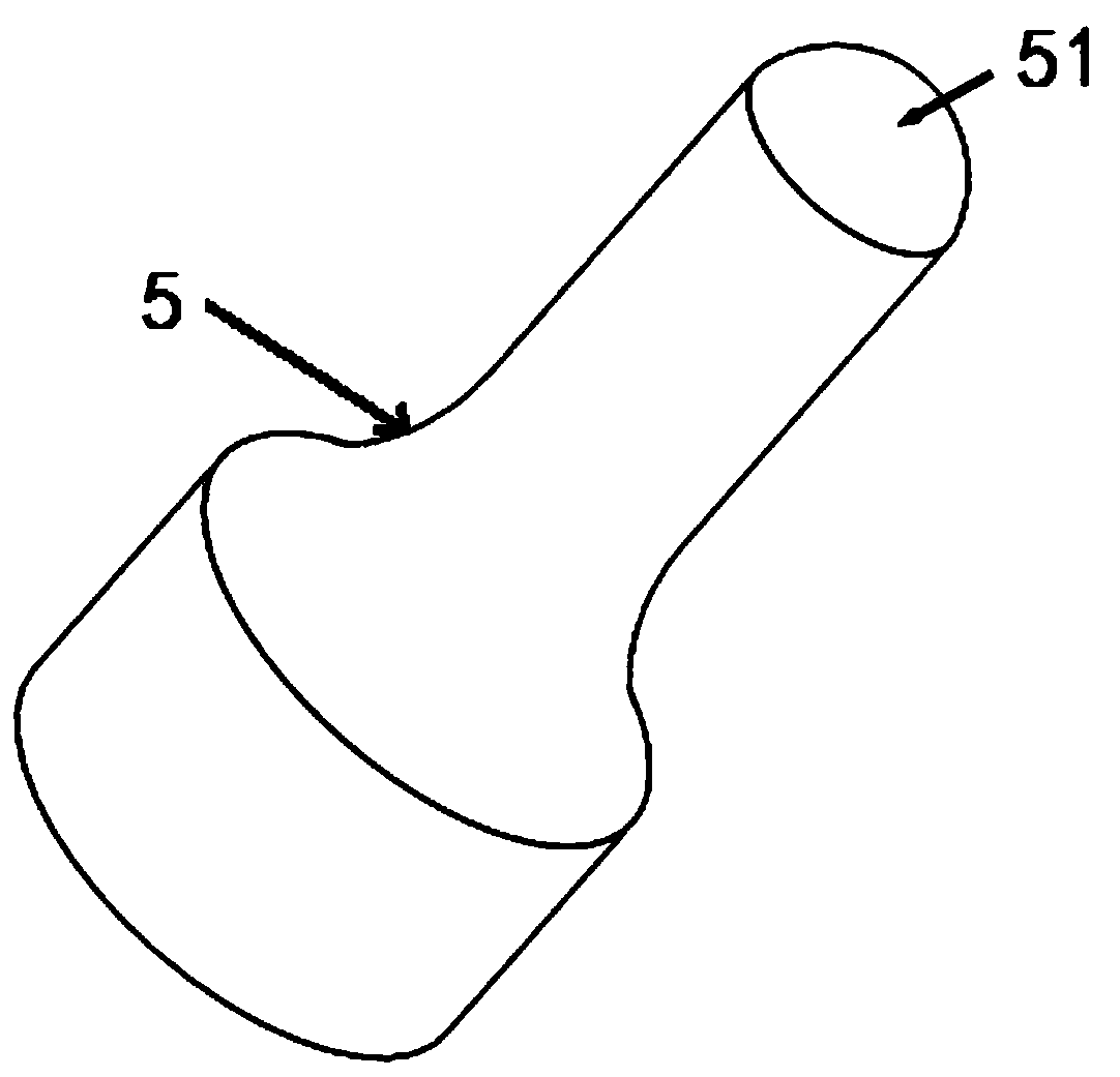
[0030] (2) Adjust the position of the stirring needle 3 of the double-shoulder friction stir welding stirring head so that it is aligned with the butt joint of the workpiece 1, and then adjust the ultrasonic tool at the bottom of the lower shoulder 4 of the double-shoulder friction stir welding stirring head The position of the ultrasonic tool head 5 is coaxial with the lower shaft shoulder 4, and a small upward pressure (0.1MPa-1MPa) is applied to the ultrasonic tool head 5 to make the ultrasonic tool head 5 The head 5 and the lower shoulder 4 are in a pressed state during the welding process.

[0031] (3)...


PUM


Abstract

The invention belongs to the technical field of welding, and particularly relates to an ultrasonic coaxial assisted dual-shaft-shoulder friction stir welding method. The ultrasonic coaxial assisted dual-shaft-shoulder friction stir welding method comprises the following steps: (1) placing a to-be-welded workpiece on a welding platform in a butt-joint form, and clamping and fixing a workpiece; (2)regulating a stirring needle of a dual-shaft-shoulder friction stir welding head to align to the butt-joint position of the workpiece, regulating an ultrasonic tool bit and a lower shaft shoulder to be on coaxial positions, and enabling the ultrasonic tool bit and the lower shaft shoulder to be in a pressing state in a welding process; (3) firstly starting the dual-shaft-shoulder friction stir welding head, then, starting the ultrasonic generator, and enabling the dual-shaft-shoulder friction stir welding head and the ultrasonic generator to synchronously move relative to the workpiece to forma friction stir welding seam to realize welding while the stirring needle and the ultrasonic tool bit are in a stable coupling state. A way of applying coaxial ultrasonic vibrations to the bottom ofthe lower shaft shoulder of the dual-shaft-shoulder friction stir welding head is adopted, so that the method increases an ultrasonic energy utilization rate and guarantees quality of a welded joint.

Description

technical field [0001] The invention belongs to the technical field of welding, and in particular relates to an ultrasonic coaxial auxiliary double-shoulder friction stir welding method. Background technique [0002] Friction stir welding (FSW) belongs to a solid phase joining method, which can obtain higher quality welded joints than conventional fusion welding methods, and is especially suitable for structural manufacturing fields such as aluminum alloys and magnesium alloys. Since the method was invented by the British Welding Institute in 1991, it has been widely used in rail transportation, aerospace, shipbuilding and other fields. However, in the traditional friction stir welding process, a large pressure is often applied, so the back of the workpiece usually needs to be rigidly supported, which will bring problems such as difficulty in clamping and high cost of fixtures. At this time, the double-shoulder friction stir welding technology came into being as a new type ...

Claims


Application Information

Patent Timeline
Patent Type & Authority Applications(China)
IPC IPC(8): B23K20/12B23K20/10
CPCB23K20/10B23K20/122
Inventor 刘积厚牛红伟卢雅琳丛孟启刘骁王健
Owner JIANGSU UNIV OF TECH
Why Eureka
Try Eureka