Gluing device for plywood processing

A technology for wood plywood and top plate, which is used in wood processing appliances, wood veneer joining, plywood presses, etc., can solve the problems of increasing the workload of the staff and inconvenient use, and achieves improving extrusion quality and reducing work. quantity, the effect of ensuring stability

Inactive Publication Date: 2020-01-14
湖北天莱木业有限公司
View PDF0 Cites 3 Cited by
  • Summary
  • Abstract
  • Description
  • Claims
  • Application Information

AI Technical Summary

Problems solved by technology

[0003] At present, the plates are glued with adhesive, then put into the mold, and then extruded, and then taken out from the mold after extrusion, which greatly increases the workload of the staff and is not convenient for people to use.

Method used


Image

  • Gluing device for plywood processing
  • Gluing device for plywood processing
  • Gluing device for plywood processing

Examples


Embodiment 1

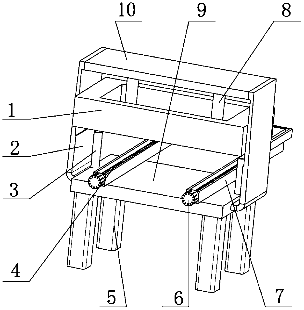
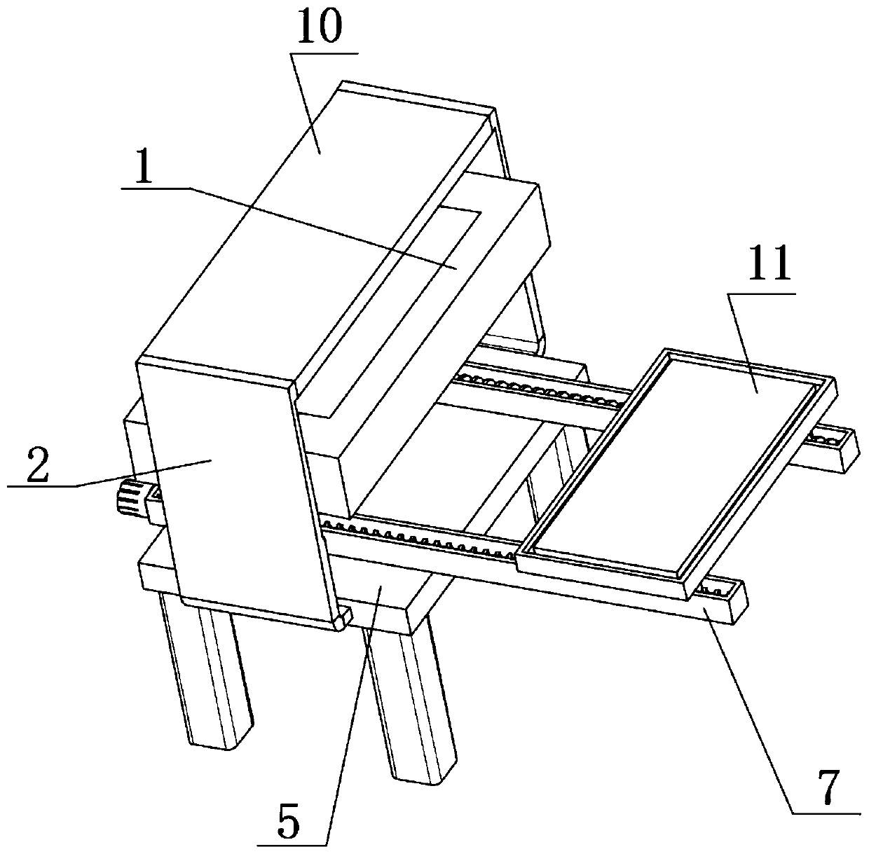
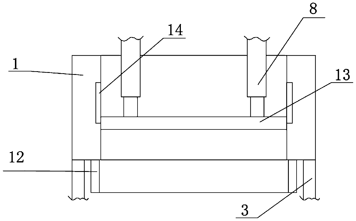
[0027] refer to Figure 1-3 , a gluing device for wood plywood processing, comprising a base 9 and four supporting legs 5, both sides of the outer wall of the top of the base 9 can be connected with supporting columns 7 by bolts, and the outer wall of the top of the supporting column 7 is provided with a rectangular groove, two rectangular grooves The inner wall of the end is rotatably connected with the same screw rod 4 placed horizontally, and the outer walls of the two screw rods 4 are rotatably connected with sliding blocks, and the top outer walls of the two sliding blocks can be connected with the same fixed plate 11 by bolts. 11 The outer wall of the top is provided with limited slots, and the four supporting legs 5 are respectively fixed to the four corners of the outer wall at the bottom of the base 9 by bolts. The outer wall at one end of the support column 7 can be connected with the motor 6 by bolts, and the output shaft of the motor 6 is connected to the outer wall...

Embodiment 2

[0031] refer to Figure 1-4 , a kind of gluing device for wood plywood processing. Compared with Embodiment 1, this embodiment also includes a sliding plate 15 slidingly connected to the inner wall of the limiting groove on the outer wall of the top of the fixed plate 11, and the outer wall of the bottom of the sliding plate 15 can be connected by bolts. Buffer spring 16, the outer wall of the bottom of buffer spring 16 is fixedly connected with the bottom inner wall of the limiting groove by bolts.

[0032] Working principle: By setting the sliding plate 15 and the buffer spring 16, the limit groove on the fixed plate 11 can be protected, preventing external debris and glue from entering the limit groove, ensuring accurate positioning, and improving the shape of the splint. quality.


PUM


Abstract

The invention discloses a gluing device for plywood processing, which includes a base and four support feet, wherein support pillars are mounted on both sides of the outer wall at the top of the base;a rectangular groove is formed in the outer wall of the top of each support pillar; a same horizontally placed screw rod is rotationally connected onto the inner walls at the two ends of each rectangular groove; sliding blocks are rotationally connected with the peripheral outer walls of the two screw rods through threads; a same fixing plate is mounted at the top outer walls of the two sliding blocks; a limiting groove is formed in the top outer wall of each fixing plate; a motor is mounted on the outer wall at one end of each support pillar; the output shaft of the motor is fixedly connected with the outer wall at one end of each screw rod; connecting plates are mounted on the outer walls on the two sides of the base. According to the invention, the motors, the support pillars, the screw rods, the sliding blocks and the fixing plate are arranged, the plywood to be subjected press fitting is stored, and then is moved to be position below a protective frame, following-up extrusion isfacilitated, and workload of staff is reduced.

Description

technical field [0001] The invention relates to the technical field of wood splint processing, in particular to a gluing device for wood splint processing. Background technique [0002] Plywood, also known as plywood, is commonly known as thin core board in the industry. It is formed by thermal pressing of three or more layers of 1 mm thick veneer or sheet adhesive. It is the most commonly used material for handmade furniture. Plywood is a three-layer or more than three-layer thin board made of logs that are peeled into veneers or sliced ​​into thin wood, and then glued with adhesives. It is usually made of odd-numbered veneers, and the fiber directions of adjacent veneers are arranged perpendicular to each other and glued together. [0003] Now all are that the plate is glued with adhesive, then put into the mould, and then it is extruded, and after extrusion, it will be taken out from the mould, which greatly increases the workload of the staff and is not convenient for...

Claims


Application Information

Patent Timeline
Patent Type & Authority Applications(China)
IPC IPC(8): B27D1/08B27D3/00
CPCB27D1/08B27D1/083B27D3/00
Inventor 张荣华
Owner 湖北天莱木业有限公司
Why Eureka
Try Eureka