Protection film tearing system

A technology of protective film and film system, which is applied in the direction of layered products, lamination auxiliary operation, lamination, etc. It can solve the problems of foreign matter caused by friction, poor tearing effect, and increased tearing time, so as to eliminate foreign matter and improve tearing time. Effect of Membrane Efficiency and Effectiveness

Pending Publication Date: 2020-01-14
SHENZHEN JT AUTOMATION EQUIP CO LTD
View PDF0 Cites 5 Cited by
  • Summary
  • Abstract
  • Description
  • Claims
  • Application Information

AI Technical Summary

Problems solved by technology

These screens need to be moved in multiple spaces during the manufacturing process before they are finished as finished products. However, during the handling process, because the surface of the screen is easily polluted or damaged, it is necessary to attach a protective film to the surface of the screen before moving it. These protective films need to be torn off before the next process, so a device that automatically separates the protective film from the surface of the screen is required
[0003] The existing protective film tearing device includes a screen adsorption fixing plate that absorbs and fixes the back of the screen with a protective film and a roller separation device that separates the protective film from the fixed screen. In the same direction, use the roller separation device to stick the protective film and separate it from the screen body. The speed of the rollers of this film tearing device is low when entering, and the products on the adsorption platform are easy to lift with the rollers, which also leads to protection when the protective film is not separated. When the film is in contact with the fixing fixture, the adhesive will rub against the fixing fixture to produce foreign matter, which will increase the tearing time, resulting in low tearing efficiency and poor tearing effect

Method used


Image

  • Protection film tearing system
  • Protection film tearing system
  • Protection film tearing system

Examples


Embodiment Construction

[0020] The following will clearly and completely describe the technical solutions in the embodiments of the present invention with reference to the accompanying drawings in the embodiments of the present invention. Obviously, the described embodiments are only some, not all, embodiments of the present invention. Based on the embodiments of the present invention, all other embodiments obtained by persons of ordinary skill in the art without making creative efforts belong to the protection scope of the present invention.

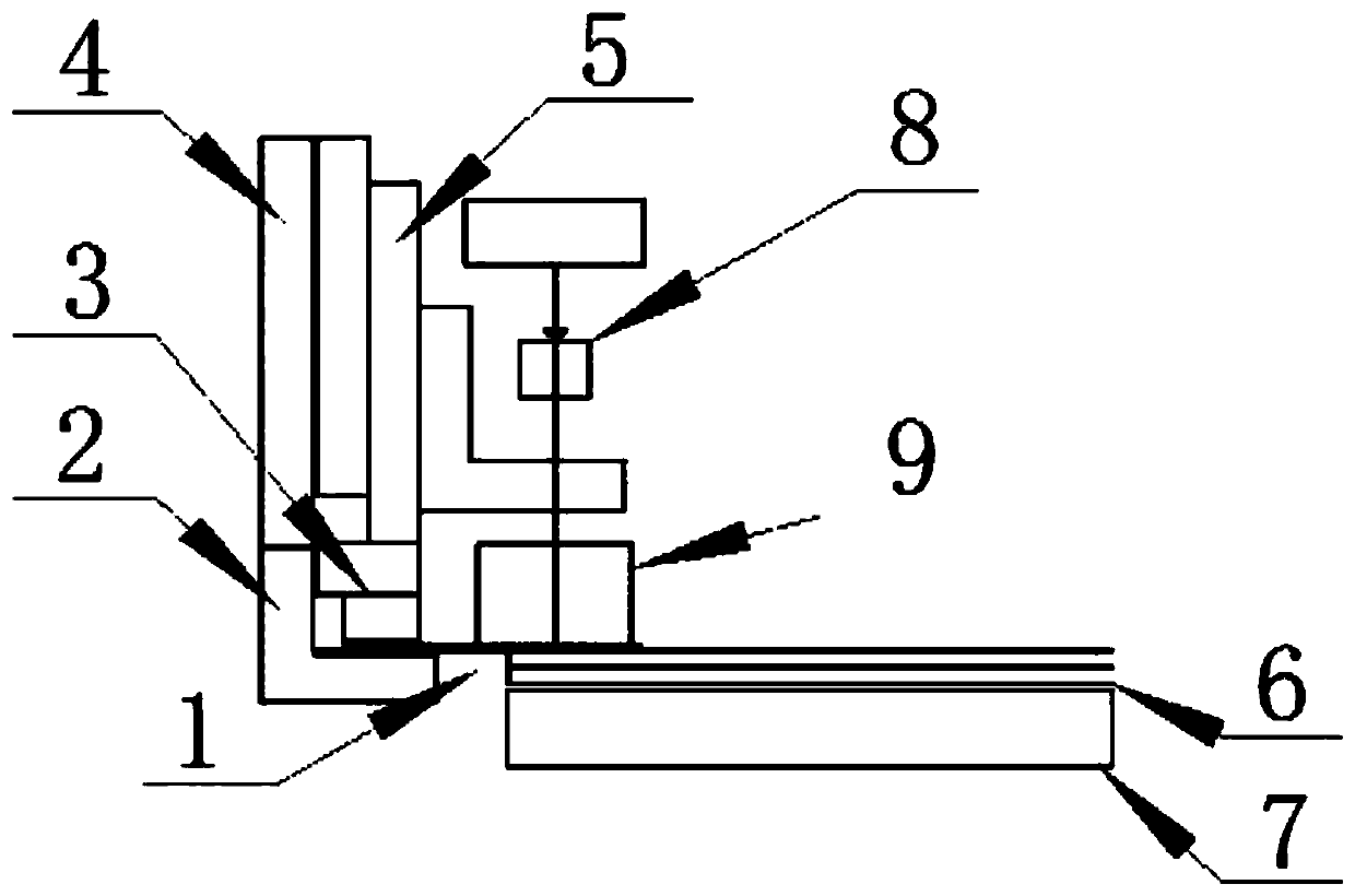
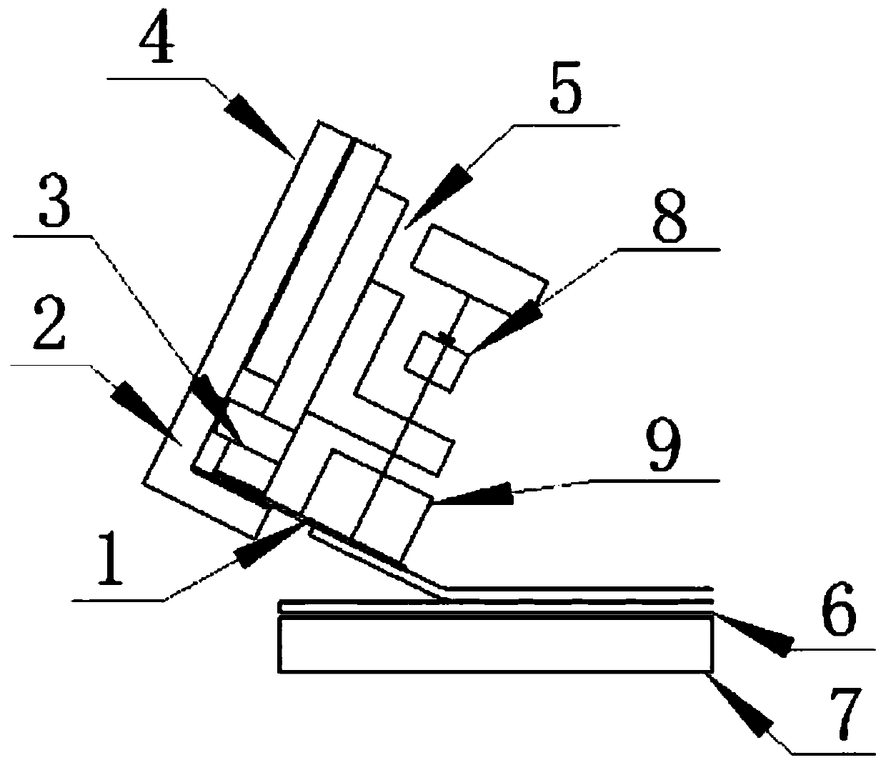
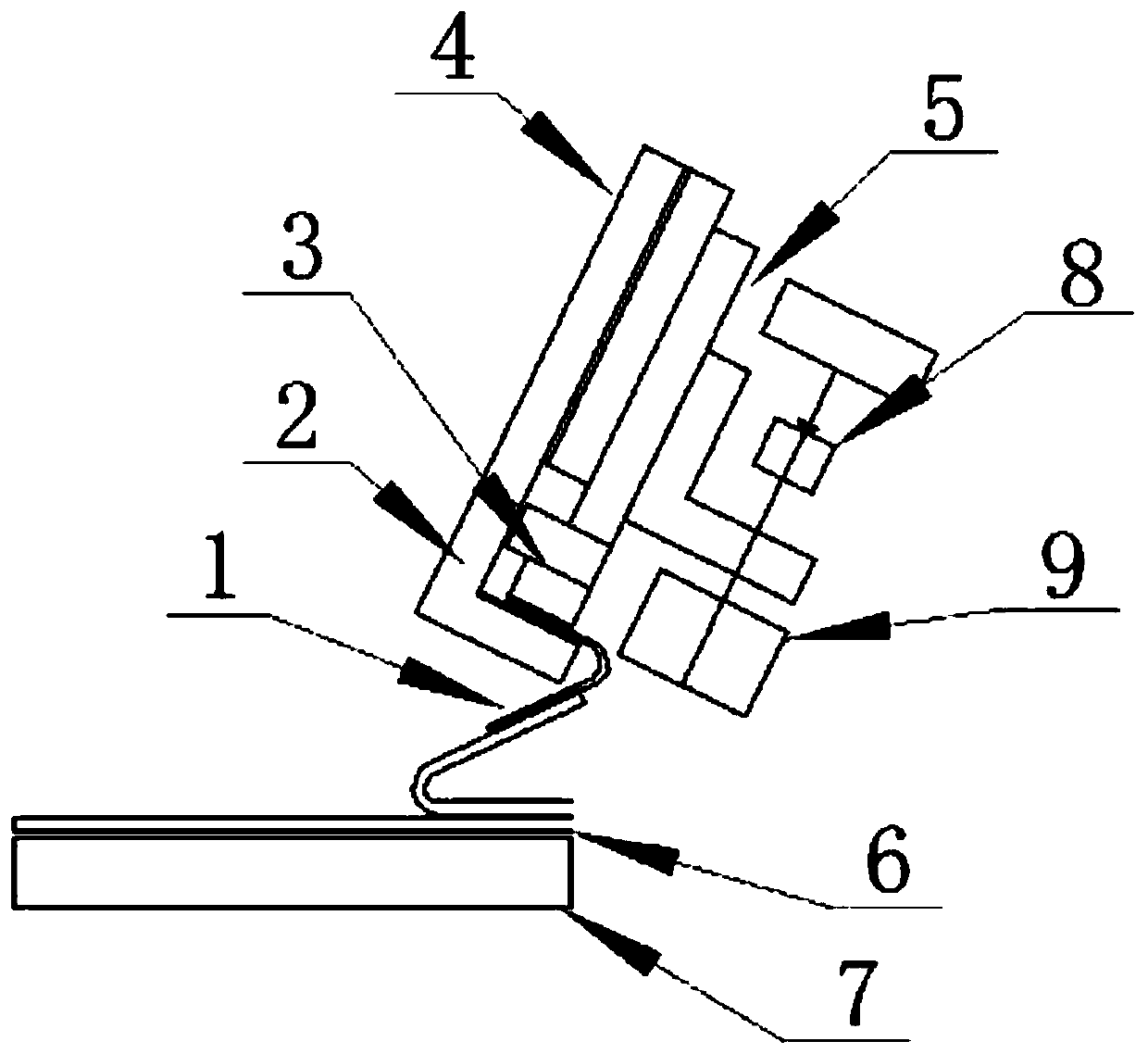
[0021] Please refer to Figure 1 to Figure 3 , figure 1 It is a schematic diagram of the overall structure in the initial state of a specific embodiment provided by the present invention; figure 2 for figure 1 The overall structure shown is in working condition; image 3 for figure 1 Overall structure shown in end state

[0022] In a specific embodiment provided by the present invention, the protective film tearing system mainly includes an easy-to-tear ...


PUM


Abstract

The invention discloses a protection film tearing system, which comprises an easy-to-tear sticker, a first clamping part, a second clamping part, a mounting plate and a clamp driving device, wherein the first clamping part is mounted on the mounting plate, the clamp driving device is mounted on the mounting plate, the second clamping part is arranged at the telescopic end of the clamp driving device so as to make the first clamping part and the second clamping part form a clamp for mounting the easy-to-tear sticker, and the sticking part of the easy-to-tear sticker can be connected to the protection film of a to-be-treated product in a sticking manner. According to the invention, with the protection film tearing system, the first clamping part and the second clamping part clamp the non-sticky part of the easy-to-tear sticker, the protection film is adhered through the sticking part of the easy-to-tear sticker, and the clamping part is displaced through the horizontal moving structure commonly used in the automatic equipment industry to achieve the separation operation of the protection film and the to-be-treated product, so that the defect that the product is brought up in a rollerfilm tearing mode is overcome while the foreign matter brought by a friction force separation mode is eliminated so as to improve the film tearing efficiency and the film tearing effect.

Description

technical field [0001] The invention relates to the technical field of display screen manufacturing, in particular to a protective film tearing system. Background technique [0002] In recent years, the types of screens used in the display component manufacturing industry tend to be diversified, including Liquid Crystal Display (liquid crystal display), Organic Light Emitting Diode (organic light emitting diode) and TouchScreen Panel (touch screen). These screens need to be moved in multiple spaces during the manufacturing process before they are finished as finished products. However, during the handling process, because the surface of the screen is easily polluted or damaged, it is necessary to attach a protective film to the surface of the screen before moving it. These protective films need to be torn off before the next process, so a device that automatically separates the protective film from the surface of the screen is required. [0003] The existing protective film...

Claims


Application Information

Patent Timeline
Patent Type & Authority Applications(China)
IPC IPC(8): B32B38/10
CPCB32B38/10
Inventor 陈东徐德勇敬锟王恒钰莫曜熙
Owner SHENZHEN JT AUTOMATION EQUIP CO LTD
Why Eureka
Try Eureka