Material turnover device with height automatic to adjust

An automatic adjustment and height technology, applied in the direction of lifting device, lifting equipment safety device, lifting frame, etc., can solve the problems of reducing work intensity, high work intensity, inconvenient material retrieval, etc., to reduce work intensity, reduce labor intensity, The effect of easy retrieval

Inactive Publication Date: 2020-01-14
中电装备山东电子有限公司
View PDF5 Cites 6 Cited by
  • Summary
  • Abstract
  • Description
  • Claims
  • Application Information

AI Technical Summary

Problems solved by technology

[0005] The invention provides a material turnover device that can automatically adjust the height, which is used to solve the problems of inconvenient material retrieving and high working intensity in the prior art, and achieves the beneficial effects of facilitating retrieving materials and reducing working intensity

Method used


Image

  • Material turnover device with height automatic to adjust
  • Material turnover device with height automatic to adjust
  • Material turnover device with height automatic to adjust

Examples


Embodiment 1

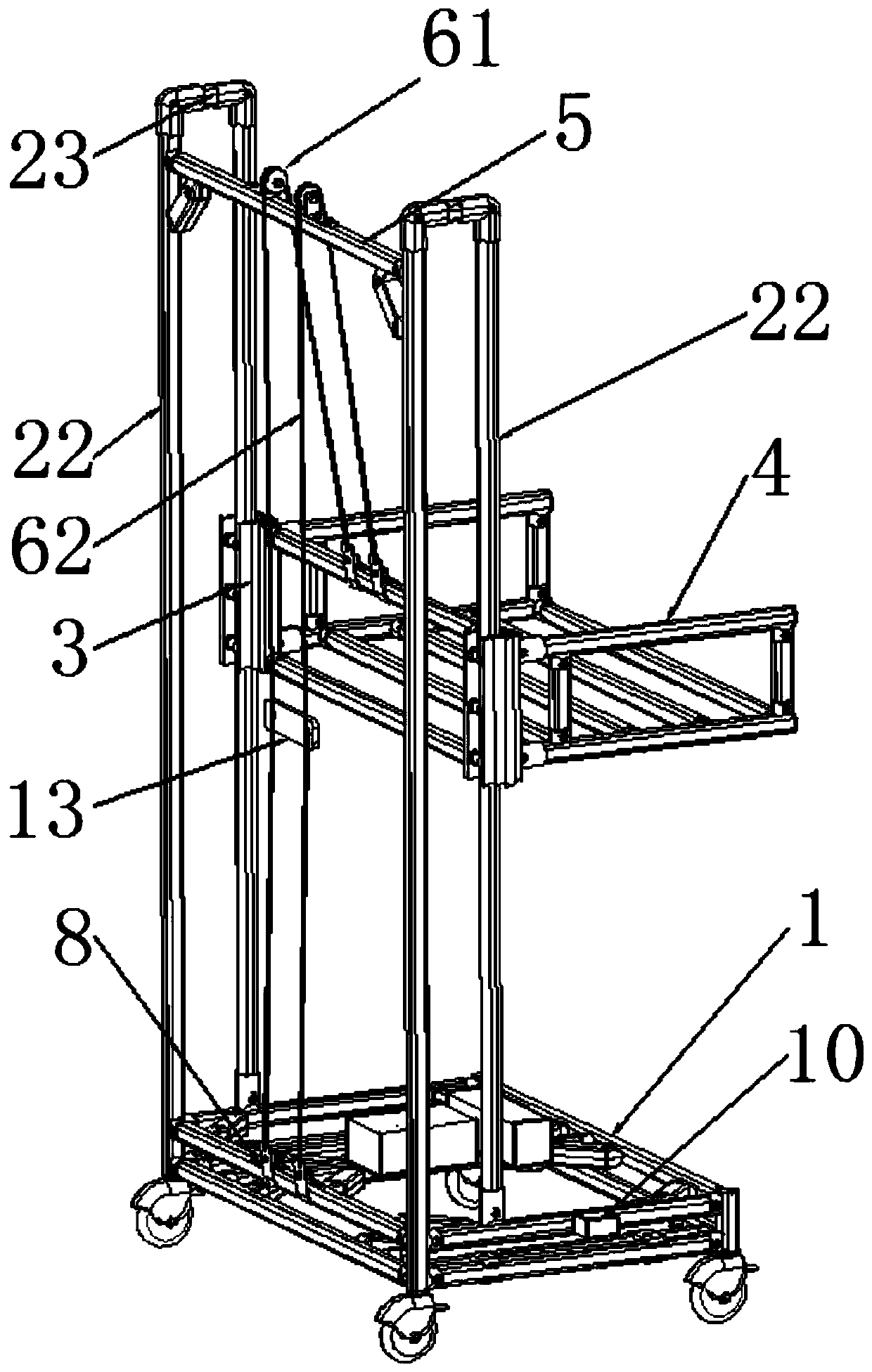
[0036] A material turnover device with automatic height adjustment, such as figure 1 As shown, a movable base bracket 1 is included, and the base bracket 1 is used to move the device; the base bracket 1 is provided with a guide support frame, and one side of the guide support frame is provided with a guide seat 3 for sliding cooperation. When the guide seat 3 slides, The guide support frame limits its movement direction; the guide seat 3 is provided with a rack 4, and the guide seat 3 moves to drive the storage rack 4 to move; a support rod 5 is installed on the upper part of the guide support frame, and a pulley block is arranged on the support rod 5, and the pulley block makes the wire rope 62 move. The movement is smoother; the pulley block includes a fixed pulley 61 and a wire rope 62 wound on the fixed pulley 61, one end of the wire rope 62 is connected to the rack 4, and the wire rope 62 gives the moving force of the rack 4; the base bracket 1 is installed with a high ela...

Embodiment 2

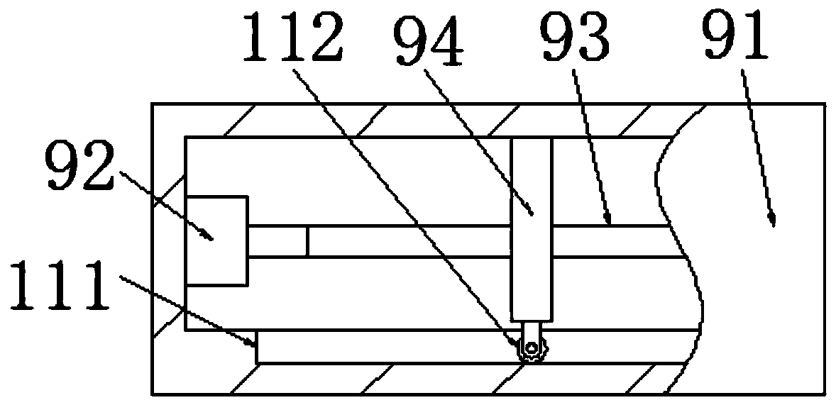
[0047] like image 3 and Figure 4 As shown, the adjustment mechanism includes a casing 91, an electric push rod 95 and a counterweight 94, the casing 91 is mounted on the base bracket 1, the electric push rod 95 is connected with the controller, and the controller controls the electric push rod 95. Work; a counterweight 94 is installed on the movable end of the electric push rod 95, and the electric push rod 95 drives the counterweight 94 to move. When the controller controls the adjustment mechanism to adjust, the controller activates the electric push rod 95, and the movable end of the electric push rod 95 expands / contracts, thereby driving the counterweight 94 to move.

Embodiment 3

[0049] On the basis of Example 1 and Example 2, as Figure 9 As shown, a limit rod assembly is installed on the guide support frame, and the limit rod assembly limits the position of the operator when placing the material; the limit rod assembly includes a limit support rod 121 and a telescopic rod 122, and the limit support rod 121 A telescopic rod 122 is installed on the bottom surface; the movable end of the telescopic rod 122 is connected to the rack 4 , and the telescopic rod 122 expands and contracts with the movement of the material to ensure that the position limit function is always played.

[0050] like Figure 9 As shown, there are three sets of the limiting components, that is, the left side and the front and rear sides of the rack 4 are installed. When placing materials, operators can ensure accurate placement. In this case, there is also a tilt problem in the x-axis direction. In order to solve this problem, the level 10 is arranged in the x-axis direction of ...


PUM


Abstract

The invention provides a material turnover device with height automatic to adjust. The device comprises a movable base support, wherein a guide supporting frame is arranged on the base support, a guide base is arranged on one side of the guide supporting frame in a sliding fit mode, an object storage frame is arranged on the guide base, the device is characterized in that a supporting rod is mounted on the upper part of the guide supporting frame, a pulley block is arranged on the supporting rod, the pulley block comprises a fixed pulley and a steel wire rope wound around the fixed pulley, oneend of the steel wire rope is connected with the object storage frame, the base support is provided with a high elastic rope, the other end of the steel wire rope is connected with the high elastic rope, the base support is provided with a detection mechanism for detecting inclination and an adjustment mechanism for adjusting the inclination, and the detection mechanism comprises a level meter used for detecting the inclination of the base support, a self-powered controller and an alarm device, wherein the level meter and the alarm device are both connected with the controller.

Description

technical field [0001] The invention belongs to the technical field of material storage and transfer, in particular to a material turnover device that can automatically adjust the height. Background technique [0002] At present, in the process of product production and processing, most of the materials to be assembled are contained in material racks with a fixed height. The height of these material racks is fixed and cannot be adjusted. Personnel cannot pick and place materials normally. [0003] With the consumption of materials, the materials on the material rack will become less and less, which leads to the need for operators to constantly adjust their working posture, and the operators cannot work at the most suitable height, which affects work efficiency and improves labor intensity. [0004] In addition, in the process of use, there are situations where the placement of the materials is not standardized by the operators. Once multiple materials are placed irregularly...

Claims


Application Information

Patent Timeline
Patent Type & Authority Applications(China)
IPC IPC(8): B66F7/02B66F7/28B66F17/00
CPCB66F7/02B66F7/28B66F17/006
Inventor 刘凤鸣时光王宏强牛中庆徐震王焕贞王成名常玖品高强王晶师
Owner 中电装备山东电子有限公司
Why Eureka
Try Eureka