
High-pressure cleaning device

A high-pressure cleaning and equipment technology, applied in mechanical equipment, cleaning methods and utensils, cleaning methods using liquids, etc., can solve the problems of large size, inability to meet, complex structure of annular plunger cavity, etc., to achieve easy portability, good cooling , the effect of small size

Pending Publication Date: 2020-01-14
CHANGZHOU GLOBE CO LTD
View PDF0 Cites 0 Cited by
  • Summary
  • Abstract
  • Description
  • Claims
  • Application Information

AI Technical Summary

Problems solved by technology

However, the structure of the annular plunger cavity is relatively complex and the size is large, and it is generally used for non-handheld high-pressure cleaning equipment, which cannot meet the requirements of the handheld high-pressure cleaning equipment for the structure of the plunger cavity.

Method used


Image

  • High-pressure cleaning device
  • High-pressure cleaning device
  • High-pressure cleaning device

Examples


Embodiment Construction

[0032] In order to make the object, technical solution and advantages of the present invention clearer, the present invention will be described in detail below in conjunction with the accompanying drawings and specific embodiments.

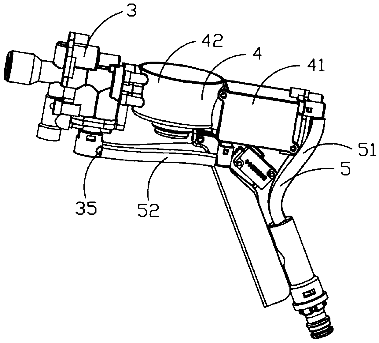
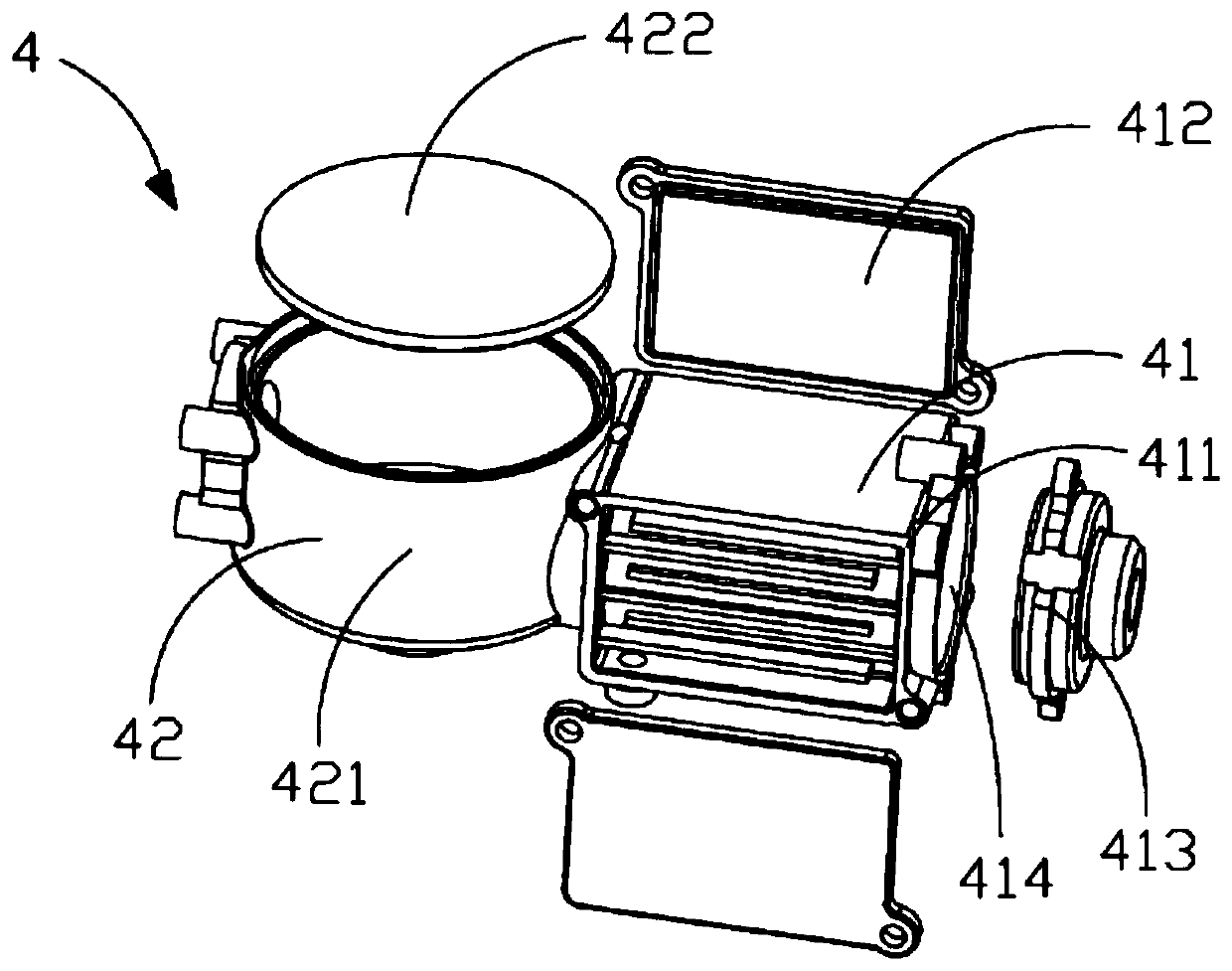
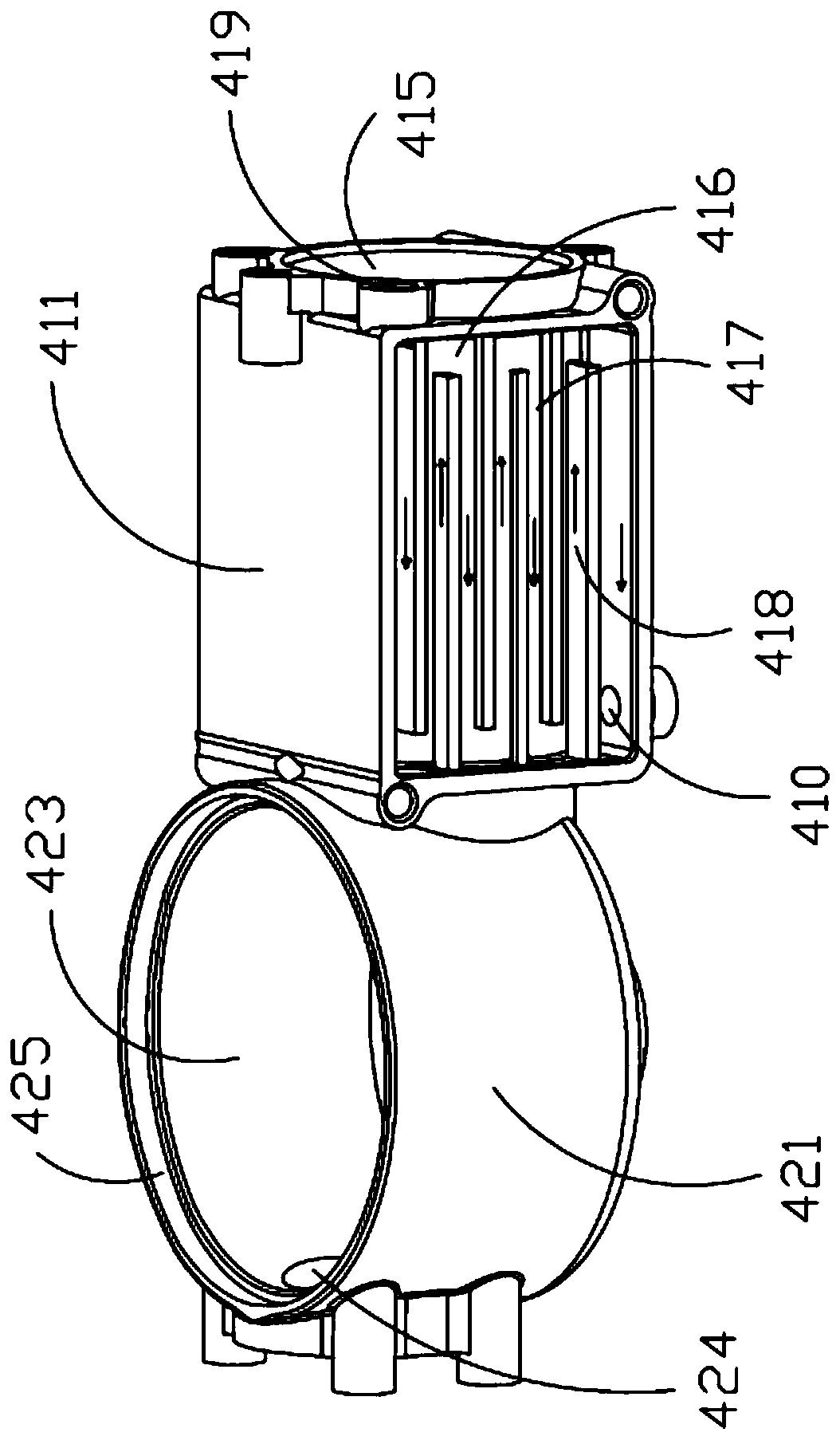
[0033] Please combine Figure 1 to Figure 5 As shown, the high-pressure cleaning equipment of the present invention includes a motor assembly 1 , a transmission assembly 2 driven by the motor assembly 1 , a pump assembly 3 connected to the transmission assembly 2 , a base 4 , a pipeline assembly 5 and a switch assembly 6 .

[0034] Please refer to Figure 5 As shown, the motor assembly 1 includes a motor shaft 11 and a motor stator and rotor assembly 12, and the motor assembly 1 is a brushless DC motor. On the one hand, the brushless DC motor optimizes the water cooling method of the motor stator and rotor assembly 12 while reducing the size of the motor; on the other hand, the brushless DC motor reduces the number of pipeline components while en...


PUM


Abstract

The invention provides a high-pressure cleaning device which comprises a motor assembly, a transmission assembly driven by the motor assembly, a pump assembly connected with the transmission assembly,a machine base and a pipeline assembly. The machine base comprises a motor shell for containing the motor assembly and a transmission box for containing the transmission assembly. Independent coolingparts are arranged on the two sides of the motor shell. Compared with the prior art, by arranging the independent cooling parts on the two sides of the motor shell, the requirements of the handheld type high-pressure cleaning device for the structure of the cooling parts are met, and the high-pressure cleaning device is small in size, high in efficiency, good in cooling and convenient to carry.

Description

technical field [0001] The invention relates to the technical field of cleaning equipment, in particular to a high-pressure cleaning equipment. Background technique [0002] At present, there are mainly two heat dissipation methods for high-pressure cleaning equipment on the market. One is to use fans to cool the motor, and the other is to use water-cooling channels to cool the motor. [0003] The fan cooling method is to set a ventilation slot structure on the whole product, which has low heat dissipation efficiency and poor cooling effect. In addition, during use, due to the fact that the ventilation tank is easy to enter water and the high-pressure cleaning equipment has a low waterproof level, it is easy to affect the operation and safety of the electrical components inside the machine. [0004] Therefore, the existing high-pressure cleaning equipment mainly adopts the water-cooling channel cooling method. The cooling method of the water-cooling channel is to set an an...

Claims


Application Information

Patent Timeline
Patent Type & Authority Applications(China)
IPC IPC(8): F04B53/08F04B17/03
CPCF04B53/08F04B17/03F04B53/16F04B53/22F04B17/06B08B3/026B08B2203/0223B08B2203/027F04B39/064F04B9/045F04B19/22
Inventor 赵春林
Owner CHANGZHOU GLOBE CO LTD
Learn More