
An aerospace extravehicular power divider

A power divider and aerospace technology, applied in waveguide-type devices, circuits, connecting devices, etc., can solve the problems of inability to apply the temperature environment outside the spacecraft, the power divider cannot be applied, and the irradiation environment cannot be used for a long time. Simple and easy to produce, expand the application field and scope, good economic effect

Active Publication Date: 2021-03-16
中国电子科技集团公司第九研究所
View PDF13 Cites 0 Cited by
  • Summary
  • Abstract
  • Description
  • Claims
  • Application Information

AI Technical Summary

Problems solved by technology

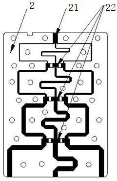
[0003] However, if the power divider designed and manufactured by the traditional method is moved outside the aerospace cabin, there are the following problems: (1) The power divider using magnetic materials cannot be used in an environment lower than -65°C, and it cannot be applied to aerospace vehicles The temperature environment outside the cabin; (2) Due to the radiation sensitivity of the dielectric material, it cannot be used in the radiation environment for a long time; (3) Even if the radiation resistance is strengthened, it is generally used for the radiation resistance of the simple and symmetrical power divider However, there is no report on the anti-radiation reinforcement of complex and asymmetric structures such as a one-point three-power splitter structure

Method used


Image

  • An aerospace extravehicular power divider
  • An aerospace extravehicular power divider
  • An aerospace extravehicular power divider

Examples


Embodiment 1

[0040] In the present embodiment, the shell is 4 mm, the second upper shielding plate 62 and the second lower shielding plate 64 are 0.4 mm in thickness, and the thickness of the first upper shielding plate 61 and the first lower shielding plate 63 is 0.5 mm. mm, the anti-irradiation ability is: anti-irradiation radiation dose: 30Mrad (Si) / metering rate: 2 ~ 50rad / Si / s conditions; the dose of proton irradiation is not less than 10 3 Gy~10 5 Irradiated total dose of Gy; screw fixation dense 2.6×10 -3 piece / mm 2 . After -179°C liquid nitrogen to +100°C / 100 temperature shocks and -100°C to +100°C / 25.5 thermal vacuum tests, it meets the long-term use requirements of -95°C to +95°C.

Embodiment 2

[0042] The shell is 4mm, the thickness of the lead plate is 0.4mm, the thickness of the stainless steel plate is 0.5mm, and the anti-radiation ability is: anti-irradiation radiation dose: 30Mrad (Si) / metering rate: 2 ~ 50rad / Si / s conditions; withstand proton irradiation Dose not less than 10 3 Gy~10 5 Irradiated total dose of Gy; screw fixation dense 9.5×10 -3 piece / mm 2 . After -179°C liquid nitrogen ~ +100°C / 100 temperature shocks, -145°C ~ +125°C / 12.5 thermal vacuum tests and adapting to the limit temperature of -145°C ~ +125°C outside the space cabin and the total radiation dose of 30Mrad (Si ) level test, meeting the long-term use requirements of -145°C ~ +125°C.


PUM


Abstract

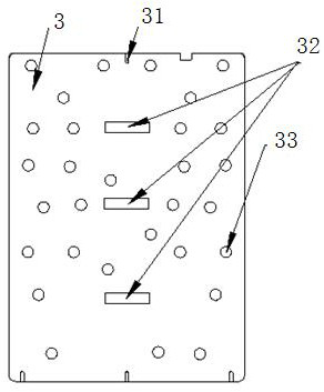
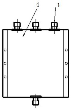
The invention discloses an aerospace extravehicular power divider, which belongs to the technical field of microwave devices and comprises a cavity and connectors connected to opposite sides of the cavity. A circuit board is arranged in the cavity, and the upper and lower sides of the cavity are All are equipped with a radiation-resistant reinforcement layer, the radiation-resistant reinforcement layer is composed of an outer layer and at least one inner layer, and the radiation-resistant reinforcement layers on the upper and lower sides are fixed by dense screw groups composed of several screws. The material of the screw is the same as that of the outer layer of the radiation-resistant reinforcement layer; the power divider of the present invention can adapt to the limit of -145°C to +125°C outside the space cabin for a long time due to the adoption of a special "suspension structure". The temperature and total radiation dose are on the order of 30Mrad (Si), which can meet the working requirements of space time (100000h); at the same time, it expands the application field and scope of the power divider; and can expand the application field of new materials, especially ultra-wide temperature materials .

Description

technical field [0001] The invention relates to the technical field of microwave devices, in particular to an aerospace power divider outside the cabin. Background technique [0002] In recent years, ultrashort wave and microwave systems have been practically applied in various commercial aerospace vehicle projects in my country. Usually, ultrashort wave and microwave systems are characterized by the synthesis and distribution of multi-channel signals to realize the array function and realize the in-phase signal transmission of multiple antennas. The volume of the satellite cabin is limited, such as moving the power divider outside the cabin, such as hanging on the antenna, which reduces the difference in amplitude and phase caused by the transmission line, can flexibly design the antenna, expand the application range of the antenna, and improve the receiving sensitivity and Ground coverage area. [0003] However, if the power divider designed and manufactured by the tradi...

Claims


Application Information

Patent Timeline
Patent Type & Authority Patents(China)
IPC IPC(8): H01P5/16
CPCH01P5/16
Inventor 周平章陈伶路谯劼崔景波朱连燕徐风清顾卫东刘中艳
Owner 中国电子科技集团公司第九研究所
Learn More