Locking device and method for oil field pumping unit brake device

A brake device and locking device technology, which is applied in mechanical equipment, brake actuators, gear transmission mechanisms, etc., can solve the problems of staff damage, aging, and brake disc immobility, etc., to solve brake sensitivity, increase practicability, non-slip effect

Active Publication Date: 2020-01-14
宋晶鑫
View PDF10 Cites 0 Cited by
  • Summary
  • Abstract
  • Description
  • Claims
  • Application Information

AI Technical Summary

Problems solved by technology

[0003] At present, most of the pumping units used in oil fields will choose the beam pumping unit. When the beam pumping unit is in use, the donkey head of the pumping unit needs to be reciprocated up and down to pump the oil up. When the oil is extracted, it is necessary to stop the work of the pumping unit. At present, the braking device is used when stopping the pumping unit. The current braking device uses the brake disc and the return spring to brake. This braking method can make the oil pumping The machine stops working, but when this device is used for a long time, the brake device will rust and age, so that if you do not pay attention, the brake disc will not be locked tightly when it is working, and the elasticity of the return spring will also be reduced. resulting in brake failure
[0004] In addition, when the pumping unit is pumping oil in the oil field, because the oil field machine moves and works on the oil field, the dust generated is relatively large, which will easily cause a large amount of dust to exist on the brake disc, and the accumulation of this dust to a certain extent will lead to brake failure. The disc and the brake disc are stuck, so that the brake disc cannot move, resulting in damage to the pumping unit and injury to the staff

Method used


Image

  • Locking device and method for oil field pumping unit brake device
  • Locking device and method for oil field pumping unit brake device
  • Locking device and method for oil field pumping unit brake device

Examples


Embodiment 1

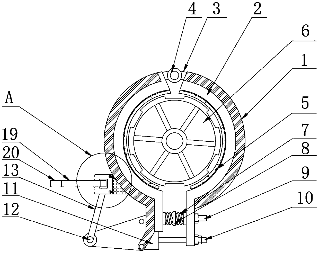
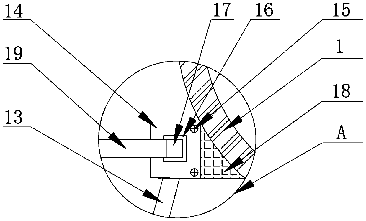
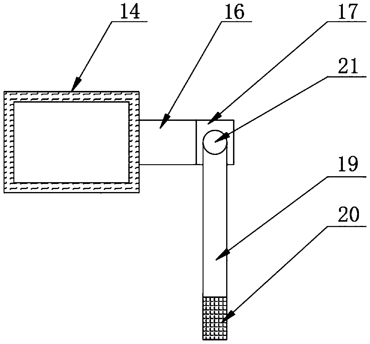
[0037] as attached Figure 1-9 The brake device locking device of the oil pumping unit shown includes a fixed disc 1, a brake disc 2, a movable block 3, a movable wheel 4, and a brake disc 6. The inner wall of the brake disc 2 is fixed with a fastening pad 5, and the brake disc 2 Back-moving spring 7 is movably installed at the bottom of the side, and fixed frame 8 is fixedly installed in the middle part of back-moving spring 7. The bottom of the other side of brake disc 2 is movably connected with spring shaft 9, and the bottom of spring shaft 9 is movably connected with movable shaft 10. The movable plate 11 is arranged on the bottom movable cover of the disc 1, and a connecting shaft 12 is fixedly installed on one side of the movable plate 11. The top of the connecting shaft 12 is welded with a connecting rod 13, and the top of the connecting rod 13 is welded with a locking box 14, and the locking box The surface of 14 is detachably installed with dismounting screw 15, and ...

Embodiment 2

[0056] Specifically compared with Embodiment 1, a positive and negative electric box 1414 is added inside the electric box 141, one end of the switch wire 1412 is fixedly connected to the positive and negative electric box 1414, and the other side of the positive and negative electric box 1414 is fixedly connected to the positive and negative electric wire 1415 , the other end of the positive and negative wire 1415 is fixedly connected with a single-axis motor 1411 .

[0057] Using the above technical means: by installing the forward and reverse electric box 1414 inside the electric box 141, when the single-axis motor 1411 is stopped and started, the positive and negative electric box 1414 is used to transmit the positive and negative currents to the single-axis motor through the positive and negative electric wires 1415 1411, so as to carry out the forward and reverse rotation of the motor shaft of the single-axis motor 1411, avoiding the brake disc 6 from being locked all the...


PUM


Abstract

The invention discloses a locking device and method for an oil field pumping unit brake device, and particularly relates to the field of oil field pumping units. The locking device comprises a fixed disc, a skid disc, a movable block, a movable wheel and a brake disc, wherein a fastening pad is fixedly installed on the inner wall of the skid disc, a reset spring is movably installed at the bottomof the side face of the skid disc, a fixing frame is fixedly installed in the middle of the reset spring, and a spring shaft is movably connected to the bottom of the other side face of the skid disc.According to the locking device and method for the oil field pumping unit brake device, by arranging a locking rotary rod, when working of the pumping unit is finished, the pumping unit utilizes thereturn spring to compress the skid plates on two sides of the brake disc, then the brake disc is stuck, and when the spring is used for a long time, the spring is slowly aged, so that the elasticity of the spring is reduced; at the moment, the locking rotary rod on one side of the skid plate works together with the reset spring, the locking rotary rod is used for clamping a locking block into a groove formed in the periphery of the brake disc, the problem of skid failures caused by the spring is avoided, and the locking problem of the brake disc is solved.

Description

technical field [0001] The invention relates to the technical field of oil pumping units, more specifically, the invention relates to a locking device and method for a brake device of an oil field pumping unit. Background technique [0002] The pumping unit is a kind of machinery and equipment for oil extraction, also known as the kowtow machine. The pumping unit is the most important lifting device in the rod pumping system. Beam pumping unit. [0003] At present, most of the pumping units used in oil fields will choose the beam pumping unit. When the beam pumping unit is in use, the donkey head of the pumping unit needs to be reciprocated up and down to pump the oil up. When the oil is extracted, it is necessary to stop the work of the pumping unit. At present, the braking device is used when stopping the pumping unit. The current braking device uses the brake disc and the return spring to brake. This braking method can make the oil pumping The machine stops working, but...

Claims


Application Information

Patent Timeline
Patent Type & Authority Applications(China)
IPC IPC(8): F16D55/2255F16D65/08F16D65/14F16D121/24
CPCF16D55/2255F16D65/08F16D65/14F16D2121/24
Inventor 宋晶鑫孟剑锋赵丹罗海生庄秀禹张衡刘正王清伟孙长海李志刘洪俊刘翠霞王立臣颜廷虎邹宏刚
Owner 宋晶鑫
Why Eureka
Try Eureka