Application of electric pneumatic braking rapid air charging device with air pressure supplement function
What is Al technical title?
Al technical title is built by PatSnap Al team. It summarizes the technical point description of the patent document.
A technology of electro-pneumatic braking and supplementary air pressure, applied in pneumatic brakes, hydrostatic brakes, hydrodynamic brakes, etc. The cylinder provides enough compressed air, etc.
Inactive Publication Date: 2016-01-13
UNIV OF JINAN
View PDF7 Cites 3 Cited by
Summary
Abstract
Description
Claims
Application Information
AI Technical Summary
This helps you quickly interpret patents by identifying the three key elements:
Problems solved by technology
Method used
Benefits of technology
Problems solved by technology
[0007] But, the deficiency of this brake machine of prior art is: when the train is running normally, the filling or exhausting of the brake main pipe is controlled by the locomotive, and when the brake main pipe is filled with wind, the compressed air will be distributed through each vehicle. Valves / control valves flow to the pressure and auxiliary cylinders of this vehicle
However, since each vehicle is only controlled by electric signals when the electro-pneumatic brake is charged, the main wind source required in the process of charging the air is still provided by the locomotive, and the role of the air cylinder is only for the purpose of cooperating with the electro-pneumatic brake. To ensure the consistency of the relief of the whole train, even if the relief cylinder is added, under the control of the electric signal, the auxiliary cylinder and the pressure cylinder of each vehicle can start to fill the air almost at the same time, but the capacity of the relief cylinder is small and The maximum pressure will not exceed the constant pressure of the brake main pipe, and it will only provide a small amount of wind for the brake main pipe. Most of the wind still needs to be provided by the locomotive, and the air filling time cannot be effectively shortened.
[0013] It can be seen that no matter whether it is an automatic air brake or an electro-pneumatic brake, after a relief, the pressure in the auxiliary air cylinder fails to return to the standard value in a short period of time, and the brake cannot be applied when braking is required. Cylinders provide enough compressed air that the brakes don't produce enough braking force, or even no braking effect at all
Method used
Image
Click on the blue label to locate the original text in one second.
Reading with bidirectional positioning of images and text.
Examples
Embodiment 1
[0125] Electro-pneumatic braking speed filling device for air pressure
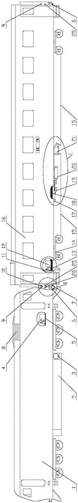
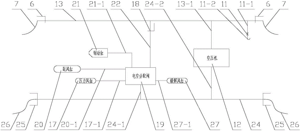
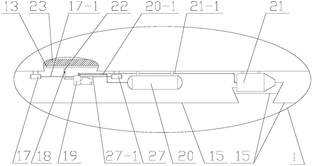
[0126] 1. The electro-pneumatic brake speed air filling device for supplementing air pressure includes: locomotive body 1, fuel tank 2, main air cylinder 3, locomotive air compressor 4, locomotive floor 5, angled plug door 6, brake hose 7 , resistance cabinet vent 8, power connector A9, jumper wire A10, emergency valve 11, air compressor with stable output pressure 12, brake main pipe 13, bogie 14, foundation brake device 15, vehicle body 16, pressure Air cylinder 17, cut-off plug 18, electro-pneumatic distribution valve 19, auxiliary air cylinder 20, brake cylinder 21, brake branch pipe 22, vehicle bottom beam 23, control cable 24, power connector B25, jumper wire B26, wind relief Cylinder 27,
[0168] The air compressor 12 with stable output pressure includes: air filter 12-1, ...
PUM
Abstract
The invention provides application of an electric pneumatic braking rapid air charging device with an air pressure supplement function, and relates to the technical field of application of carriage braking release. The application of the electric pneumatic braking rapid air charging device with the air pressure supplement function is characterized in that a locomotive supplies air to carriages; a control cable transmits a release instruction electric signal to an electric pneumatic distribution valve through a secondary control branch A, the electric pneumatic distribution valve obtains the release instruction electric signal to work, a release air pipe is connected to a braking branch pipe, and a release air cylinder conducts air charging on a braking main pipe through the release air pipe, the electric pneumatic distribution valve and the braking branch pipe; when the electric pneumatic distribution valve has a sense that the pressure of the braking main pipe is increased, and has obtained the release instruction electric signal from the secondary control branch A, a braking cylinder pipe is connected to the atmosphere; a, phase release of train braking is conducted, and b, direct release of train braking is conducted; and air charging is conducted, wherein air charging begins when train braking is released, in the process that an air compressor which conducts stable pressure output conducts air charging on the braking main pipe, when a serial control device enters the pressure maintaining position, air charging temporarily stops, and when the serial control device is located at the release position all the time, air charging is conducted to enable the constant pressure of the braking main pipe to be achieved.
Description
technical field [0001] The application of an electro-pneumatic braking speed filling device for supplementing air pressure relates to the technical field of vehicle braking relief application. Background technique [0002] my country's railway network spreads all over the country, and railway passenger transport is the mainstream means of transportation. [0003] During my country's railway operation, at 4:41 on April 28, 2008, the downlink Beijing-Qingdao passenger train T195 derailed between Wangcun and Zhoucun on the Jiaoji Line and rushed to the outside of the uplink base. At this time, the normal operation of the 5034 passenger train from Yantai to Xuzhou failed to brake enough, and finally collided with the derailed vehicle at a speed of 70 kilometers per hour, and the locomotive and the 1st to 5th carriages derailed. The Jiaoji railway train collision accident has caused 72 deaths and 416 injuries. [0004] Therefore, the train braking response time is short, and th...
Claims
Application Information
Patent Timeline
Application Date:The date an application was filed.
Publication Date:The date a patent or application was officially published.
First Publication Date:The earliest publication date of a patent with the same application number.
Issue Date:Publication date of the patent grant document.
PCT Entry Date:The Entry date of PCT National Phase.
Estimated Expiry Date:The statutory expiry date of a patent right according to the Patent Law, and it is the longest term of protection that the patent right can achieve without the termination of the patent right due to other reasons(Term extension factor has been taken into account ).
Invalid Date:Actual expiry date is based on effective date or publication date of legal transaction data of invalid patent.