
A pipeline opening and closing control device

A technology for control devices and pipelines, which is applied in the direction of valve devices, valve operation/release devices, valve details, etc. Valve service life and other issues, to achieve the effect of reduced construction and maintenance costs, easy maintenance, and reduced maintenance costs

Active Publication Date: 2021-07-20
江苏丰又环境科技有限公司 +1
View PDF0 Cites 0 Cited by
  • Summary
  • Abstract
  • Description
  • Claims
  • Application Information

AI Technical Summary

Problems solved by technology

[0004] 1. Due to the large number of sewage pools, each sewage pool needs to lay a separate pipeline to the control center. If there are one hundred sewage pools, one hundred sets of control pipelines need to be laid, and the pipelines are buried underground. Excavation, construction and maintenance are costly, difficult, long-term and labor-intensive
[0005] 2. Because the sewage in the sewage pool is corrosive to a certain extent, it has a relatively large impact on the electronic circuit, thus affecting the service life of the liquid level gauge and solenoid valve
[0006] 3. Due to the large flow of water entering the sewage pool and a lot of debris, it has an impact on the liquid level gauge, so that the liquid level gauge cannot accurately remember the high and low liquid levels, which makes the solenoid valve switch between open and closed states frequently, reducing the solenoid valve. service life

Method used


Image

  • A pipeline opening and closing control device
  • A pipeline opening and closing control device
  • A pipeline opening and closing control device

Examples


Embodiment 1

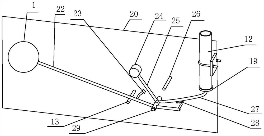
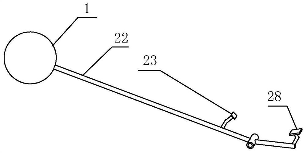
[0071] Such as figure 2 As shown, in this embodiment, the floating member 1 and the first connecting rod A22 are assembled: a hollow spherical structure is used as the floating member 1 in this embodiment, and the first connecting rod A22 includes a connecting end of the floating member and a first installation end 21 . The first connecting rod A22 is connected with the floating member 1 through the connecting end of the floating member. The first installation end 21 of the first connecting rod A22 is in the structure of a rotating sleeve A. The first connecting rod A22 is provided with a first trigger structure 23, a second The trigger structure 28, wherein the first trigger structure 23 faces the power receiving structure of the potential energy transmission mechanism, and the second trigger structure 28 faces the first connection structure 27 on the potential energy transmission mechanism.

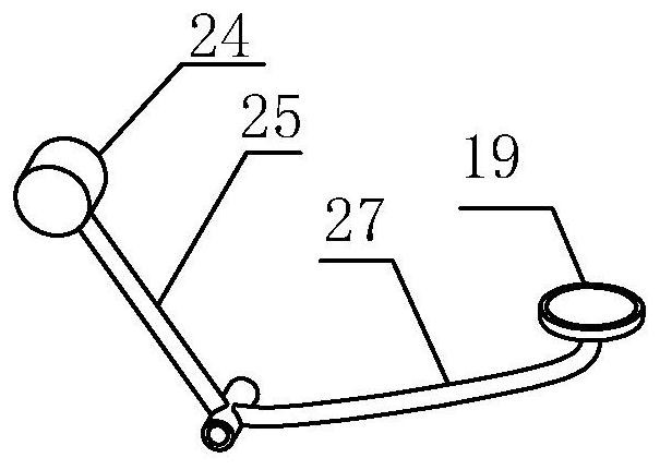
[0072] Such as image 3As shown, in this embodiment, the potential energy transmi...

Embodiment 2

[0076] In order to further improve the use effect of the present invention, prevent the pipeline closure from slowly opening or closing at a specific position due to the slow rise or fall of the floating member 1 when the liquid level rises or falls slowly, resulting in the opening and closing of the negative pressure pipe inlet. . Embodiment 2 provides a method of using multiple potential energy transmission mechanisms to realize high-level rapid full-level discharge. Prevent the pipeline blocking mechanism 19 from frequently switching between blocking the entrance of the negative pressure pipeline 12 and being away from the entrance of the negative pressure pipeline 12 due to the slow rise and fall of the liquid level when the pipeline blocking mechanism 19 is close to or away from the negative pressure pipeline 12 The situation makes the system open only at the highest point of the liquid level and close at the lowest point of the liquid level, making the opening and closin...


PUM


Abstract

The invention relates to the technical field of pipeline on-off. Disclosed is a pipeline opening and closing control device, comprising: a floating member, a first connecting rod, a potential energy transmission mechanism, and a pipeline blocking mechanism. The invention adopts the way that the floating part follows the liquid level to rise and fall to trigger the potential energy transmission mechanism to drive the pipeline blocking mechanism to control the opening and closing of the negative pressure pipeline. The whole device does not use complex program control system, electronic control system, electrification equipment, etc., and does not need to lay pipelines to the control center, which greatly simplifies the discharge system and realizes the purpose of automatic discharge. Moreover, the anticorrosion performance of components such as liquid level gauges and electronic valves adopted in the prior art is better. When multiple potential energy transmission mechanisms are used for transmission, it can also realize the functions of fast full-level discharge at high liquid level and fast closing at low liquid level, and realize the opening and closing function of high and low liquid level pipelines, replacing liquid level floats and electromagnetic The feedback and opening and closing function of the valve to the high and low liquid level. The invention is durable, easy to manufacture, install and maintain, and saves cost.

Description

technical field [0001] The invention relates to the technical field of pipeline on-off, and is especially suitable for the on-off control of sewage collection pipelines in sewage pools in domestic sewage collection systems. Background technique [0002] In the prior art, when a negative pressure suction system is used for the transfer of multi-point drainage, the following methods are usually adopted: a negative pressure pipeline connected to a negative pressure device for collecting sewage is installed in each sewage tank, and each drainage sewage tank A liquid level gauge is installed in the middle, and a solenoid valve is used to control the opening and closing of the negative pressure pipeline. The cable pipeline and the liquid level control pipeline for controlling the action of the solenoid valve are separately set up for each sewage tank, and are managed uniformly through the control center. When in use, the control center obtains the liquid level information in the s...

Claims


Application Information

Patent Timeline
Patent Type & Authority Patents(China)
IPC IPC(8): F16K31/20F16K31/44F16K1/32
CPCF16K1/32F16K31/20F16K31/44
Inventor 陈礼国张维陈云逸
Owner 江苏丰又环境科技有限公司
Learn More