
Semiconductor structure measurement and boundary feature extraction method and device

A technology of boundary features and extraction methods, applied in the direction of using radiation for material analysis, etc., can solve the problems of measurement error, low precision, and inability to realize multiple automatic measurements, etc., and achieve the effect of enhanced contrast and clear identification

Active Publication Date: 2022-08-05
YANGTZE MEMORY TECH CO LTD
View PDF22 Cites 0 Cited by
  • Summary
  • Abstract
  • Description
  • Claims
  • Application Information

AI Technical Summary

Problems solved by technology

[0003] In the prior art, measurement tools can be used to measure the general simple shape of semiconductor devices or the single and large critical dimensions of semiconductor devices, but for complex structures with small critical dimensions (such as 3D NAND) Said, the measurement tool in the prior art can not meet the needs, the main reasons are as follows:
[0004] 1. For example, when using an electron microscope to observe the channel hole in a 3D memory device, since the photo grayscale of the polysilicon channel layer and the tunneling layer filled in the channel hole are almost the same, the interface between the two cannot be distinguished, so Problems that lead to inaccurate measurements
This error in measurement results will seriously affect the process optimization and electrical performance testing of the product
[0005] 2. When using the existing technology to measure, it is necessary to observe the photos with the naked eye. For structures with complex and small critical dimensions, it is difficult to distinguish the difference manually, and there is a problem of low precision
[0006] 3. Due to the need for manual observation, continuous multiple automatic measurements cannot be realized, and there is a problem of low measurement efficiency, which affects the progress of research and development

Method used


Image

  • Semiconductor structure measurement and boundary feature extraction method and device
  • Semiconductor structure measurement and boundary feature extraction method and device
  • Semiconductor structure measurement and boundary feature extraction method and device

Examples


Embodiment Construction

[0046] The present invention will be described in more detail below with reference to the accompanying drawings. In the various figures, like elements are designated by like reference numerals. For the sake of clarity, various parts in the figures have not been drawn to scale. Additionally, some well-known parts may not be shown. For the sake of simplicity, the semiconductor structure obtained after several steps can be depicted in one figure.

[0047] It will be understood that, in describing the structure of a device, when a layer or region is referred to as being "on" or "over" another layer or region, it can be directly on the other layer or region, or Other layers or regions are also included between it and another layer, another region. And, if the device is turned over, the layer, one region, will be "under" or "under" another layer, another region.

[0048] In order to describe the situation directly above another layer, another area, the expression "directly on" o...


PUM


Abstract

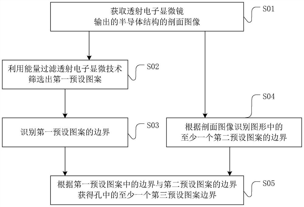
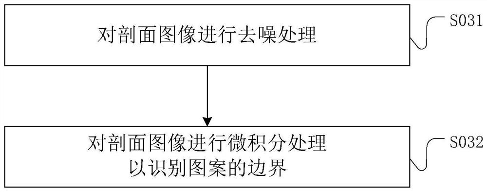
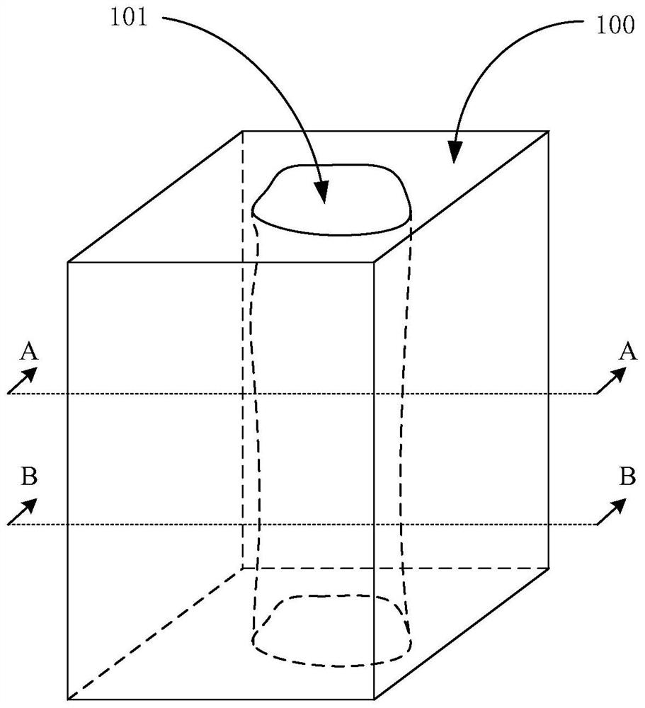
The present application discloses a semiconductor structure measurement and boundary feature extraction method and device. The boundary feature extraction method includes: acquiring a cross-sectional image of a semiconductor structure output by a transmission electron microscope, including a cross-sectional pattern of at least one hole, and the plane where the cross-sectional pattern is located is perpendicular to the axial direction of the hole; a preset pattern; and identifying the boundary of the first preset pattern, wherein the first preset pattern is composed of polysilicon in the hole. The boundary feature extraction method utilizes the special properties of the interaction between polysilicon and electrons, enhances the contrast of the first preset pattern, and achieves the purpose of clearly identifying the boundary of the first preset pattern.

Description

technical field [0001] The present invention relates to semiconductor technology, and more particularly, to a method and device for measuring and extracting boundary features of semiconductor structures. Background technique [0002] With the miniaturization of semiconductor devices, the critical dimensions of semiconductor devices have been reduced to the nanometer level, which means that the critical dimensions will determine the performance of semiconductor devices. Therefore, it is necessary to accurately measure the critical dimensions and grasp the critical dimensions at the nanometer level. The degree of change has become an indispensable link. [0003] In the prior art, the general simple topography of a semiconductor device or a single and large critical dimension of a semiconductor device can be measured by measuring tools, but for complex structures with small critical dimensions (such as 3D NAND) It is said that the measurement tools in the prior art cannot meet...

Claims


Application Information

Patent Timeline
Patent Type & Authority Patents(China)
IPC IPC(8): G01N23/04
CPCG01N23/04
Inventor 魏强民卢世峰朱宏斌张正飞夏仲仪
Owner YANGTZE MEMORY TECH CO LTD
Learn More