Communication-in-motion antenna
A communication and antenna technology in motion, applied to antennas, antenna parts, antennas suitable for movable objects, etc., can solve the problems of increased motion envelope, high overall height, loose structural layout quality distribution, etc., to achieve overall compact effect
- Summary
- Abstract
- Description
- Claims
- Application Information
AI Technical Summary
Problems solved by technology
Method used
Image
Examples
Embodiment 1
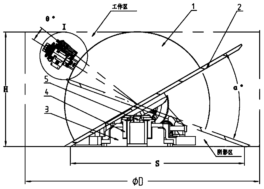
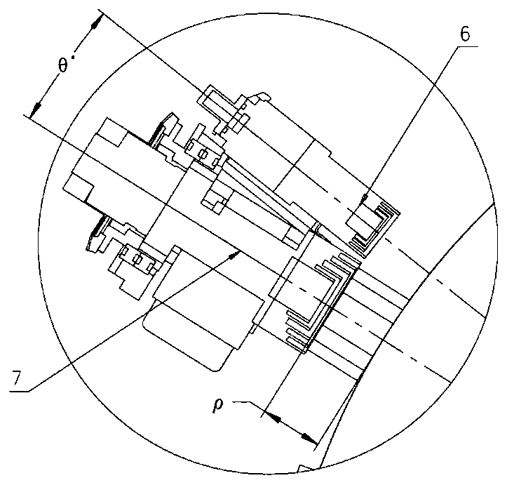
[0041] Please refer to figure 1 and figure 2 , which shows a schematic diagram of the overall structure of an embodiment of a communication antenna in motion according to the present invention. The communication antenna in motion includes:
[0042] Azimuth adjustment mechanism;
[0043] Pitch adjustment mechanism;
[0044] Antenna body, the antenna body includes:
[0045] hemispherical lens 1; and
[0046] A reflector 2, a hemispherical lens 1 is arranged on the reflective surface of the reflector 2;
[0047] a feed source, the phase center of the feed source coincides with the focus position of the antenna body, and the feed source follows the movement of the azimuth adjustment mechanism;
[0048] The pitch adjustment mechanism is arranged on the azimuth adjustment mechanism, and the antenna body is arranged on the pitch adjustment mechanism.
[0049] In the above-mentioned embodiment, the lens antenna in the existing airborne satellite is usually equipped with a whole...
Embodiment 2
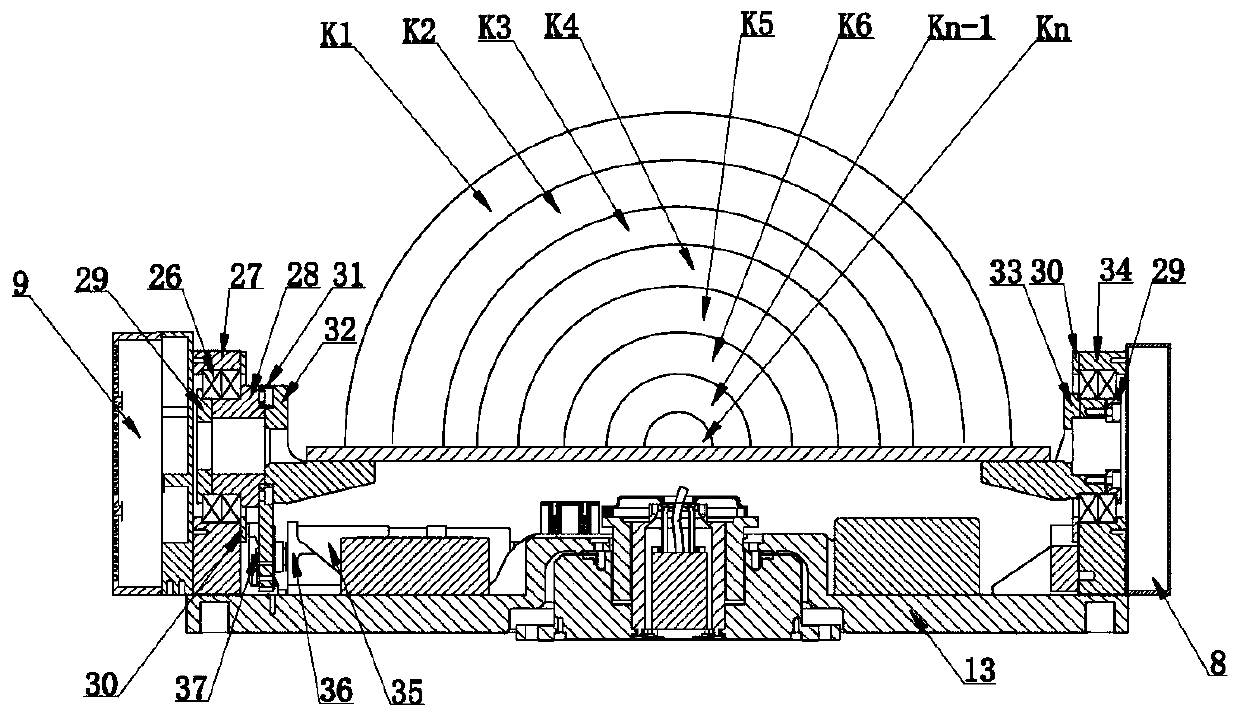
[0053] Further, please refer to image 3and Figure 8 , another embodiment of the communication antenna in motion according to the present invention, the azimuth adjustment mechanism includes: an azimuth plate 13, an azimuth adjustment motor 3, a bus ring 4 and a coaxial rotary joint 23, the bottom surface of the azimuth plate 13 has a concave cavity, The upper surface of orientation plate 13 has boss, and described concave cavity is positioned at described convex interior, and azimuth adjusting motor 3 is arranged in described concave cavity, and second encoder 5, and second encoder 5 is located at orientation plate 13 and Between the azimuth adjustment motors 3, one end of the second encoder 5 is connected to the azimuth plate 13, the other end is connected to the azimuth adjustment motor 3, the bus ring 4 is arranged between the second encoder 5 and the azimuth adjustment motor 3, and one end of the bus ring 4 is connected to the azimuth adjustment motor 3. Adjust the moto...
Embodiment 3
[0057] Further, please refer to figure 1 , another embodiment of the antenna in motion of the present invention, there is a shadow area between the reflector 2 and the azimuth adjustment mechanism, and the functional components of the pitch adjustment mechanism and the azimuth adjustment mechanism are arranged in the shadow area Inside, the shaded area is the area between the reflector 2 and the azimuth adjustment mechanism that the reflector 2 cannot touch during the movement.
[0058] In the above-mentioned embodiment, the reflector 2 is located above the azimuth adjustment mechanism. When the reflector 2 rotates at the upper end of the azimuth adjustment mechanism, a shadow area will be formed between the reflector 2 and the azimuth adjustment mechanism. The shadow area reflector 2 is Inaccessible, the inventor found that this area can be utilized to place some circuit components of the antenna, so as to reduce the overall size of the antenna.
[0059] The functional compo...
PUM
 Abstract
Description
Claims
Application Information
 - R&D
- Intellectual Property
- Life Sciences
- Materials
- Tech Scout
- Unparalleled Data Quality
- Higher Quality Content
- 60% Fewer Hallucinations
Browse by: Latest US Patents, China's latest patents, Technical Efficacy Thesaurus, Application Domain, Technology Topic, Popular Technical Reports.
© 2025 PatSnap. All rights reserved.Legal|Privacy policy|Modern Slavery Act Transparency Statement|Sitemap|About US| Contact US: help@patsnap.com


