Semiautomatic sealing machine for miniature spring-type probe

A spring-type, semi-automatic technology, applied in the field of electronic components, can solve the problems of low efficiency and poor precision, and achieve the effect of increasing the contact area, high work efficiency and simple operation

Pending Publication Date: 2020-01-14
苏州英世米半导体技术有限公司
View PDF0 Cites 1 Cited by
  • Summary
  • Abstract
  • Description
  • Claims
  • Application Information

AI Technical Summary

Problems solved by technology

[0004] The technical problem mainly solved by the present invention is to provide a semi-automatic sealing machine with a miniature spring type probe, which can solve the problems of poor precision and low efficiency of existing manual sealing machines

Method used


Image

  • Semiautomatic sealing machine for miniature spring-type probe
  • Semiautomatic sealing machine for miniature spring-type probe
  • Semiautomatic sealing machine for miniature spring-type probe

Examples


Embodiment Construction

[0035] The preferred embodiments of the present invention will be described in detail below in conjunction with the accompanying drawings, so that the advantages and features of the present invention can be more easily understood by those skilled in the art, so as to define the protection scope of the present invention more clearly.

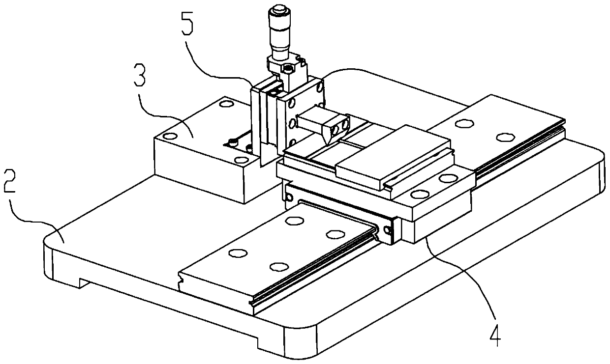
[0036] see figure 2 , the embodiment of the present invention includes:

[0037] A semi-automatic sealing machine for miniature spring-type probes, comprising: a base 2, a connecting block A3, an X-axis sliding assembly 4 and a Z-axis fine-tuning assembly 5, and the connecting block A3 and the X-axis sliding assembly 4 are arranged on the base 2 On, the Z-axis fine-tuning assembly 5 is arranged on the connection block A3;

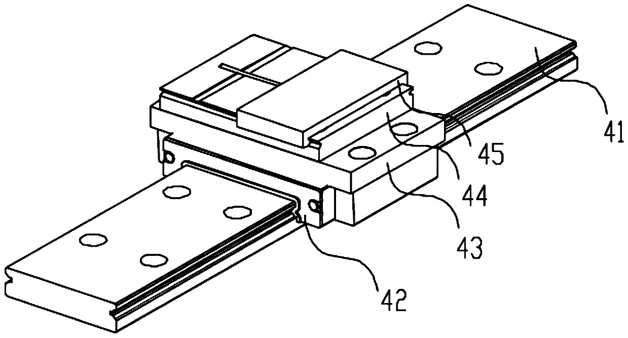
[0038] Such as image 3 , the X-axis sliding assembly 4 includes: a fixed slide 41, an X-axis slide 42, a connecting plate C43, a probe fixing base 44 and a probe fixing block 45, and the X-axis slide 42 is arranged on the ...


PUM


Abstract

The invention discloses a semiautomatic sealing machine for a miniature spring-type probe. The semiautomatic sealing machine includes a base, a connection block A, an X-axis sliding component, and a Z-axis fine-tuning component. The connection block A and the X-axis sliding component are arranged on a base. The Y-axis fine-tuning component is disposed on the connecting block A. The X-axis slidingcomponent includes: a fixed slide, an X-axis slide table, a connection plate C, a probe fixing base and a probe fixing block. The X-axis slide table is arranged on the fixed slide and can slide alongthe fixed slide. The connection plate C is disposed on the X-axis slide table. The probe fixing base is disposed on the connection plate C for holding a probe. The probe fixing block is arranged on the probe fixing base for pressing the probe. The semiautomatic sealing machine can solve the poor accuracy and the low efficiency of a traditional manual sealing machine.

Description

technical field [0001] The invention relates to the field of electronic components, in particular to a semi-automatic sealing machine for miniature spring type probes. Background technique [0002] Spring type probe is a kind of needle shaft, spring, sleeve 11 (such as figure 1 ) The three basic parts are formed after riveting and pre-pressing with precision instruments, and the needle shaft and spring are preset in the sleeve. When in use, the probe is energized or conducted, and most of it touches the copper wall obliquely downward through one end of the needle shaft. The spring bears a small amount of gravity, and the inner wall of the needle tube (copper sleeve) is required to be smooth. Normally, the spring is compressed within the sleeve. In order to prevent the deformation recovery of the spring, the sleeve needs to be sealed, and a small section of the sleeve is squeezed inward to form a sealing groove, thereby restricting the ejection of the spring. [0003] Comm...

Claims


Application Information

Patent Timeline
Patent Type & Authority Applications(China)
IPC IPC(8): H01R43/16
CPCH01R43/16
Inventor 杨晓华石光普李雷
Owner 苏州英世米半导体技术有限公司
Why Eureka
Try Eureka