Automatic control cabinet for thermal power plant

A technology for control cabinets and thermal power plants, applied in cooling/ventilation of substations/switchgears, electrical components, substations/power distribution device shells, etc., can solve problems such as inconvenient wiring, messy wires, and low efficiency, and achieve faster heat dissipation Dissipation, cleanliness, and high practicability

Inactive Publication Date: 2020-01-14
XIAN XINGYI TECH
View PDF3 Cites 3 Cited by
  • Summary
  • Abstract
  • Description
  • Claims
  • Application Information

AI Technical Summary

Problems solved by technology

[0002] With the increase of power consumption, manual operation of some working equipment in thermal power plants is extremely inefficient and can no longer meet the actual use needs. With the progress of society, thermal power plants have gradually realized automation. The existing thermal power plant automation control The cabinet is not convenient for wiring. W

Method used


Image

  • Automatic control cabinet for thermal power plant
  • Automatic control cabinet for thermal power plant
  • Automatic control cabinet for thermal power plant

Examples


Example Embodiment

[0022] The technical solutions in the embodiments of the present invention will be clearly and completely described below in conjunction with the accompanying drawings in the embodiments of the present invention. Obviously, the described embodiments are only a part of the embodiments of the present invention, rather than all the embodiments. Based on the embodiments of the present invention, all other embodiments obtained by those of ordinary skill in the art without creative work shall fall within the protection scope of the present invention.
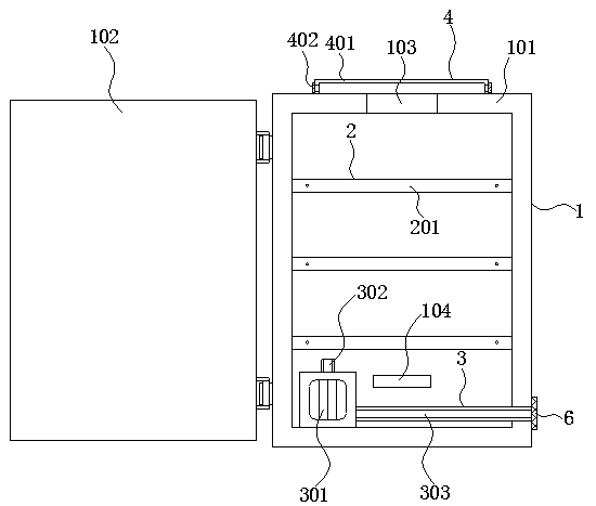
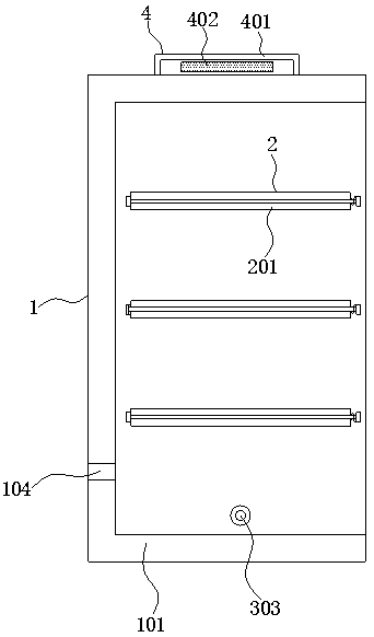
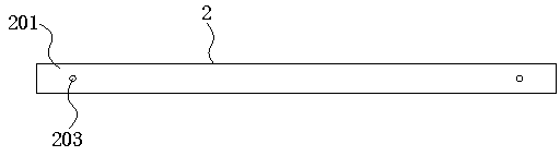
[0023] See Figure 1-5 , An automation control cabinet for thermal power plants, including cabinet assembly 1, wire harness installation assembly 2, heat dissipation assembly 3 and dustproof assembly 4. The harness installation assembly 2 is installed inside the cabinet assembly 1, and the heat dissipation assembly 3 It is installed at the bottom of the inner wall of the cabinet assembly 1, and the dust-proof component 4 is installed at ...


PUM


Abstract

The invention discloses an automatic control cabinet for a thermal power plant, and the cabinet comprises a cabinet assembly, a bunch installation assembly, a heat dissipation assembly, and a dustproof assembly; the bunch installation assembly is disposed in the cabinet assembly, the heat dissipation assembly is disposed at the bottom of the inner wall of the cabinet assembly, and the dustproof assembly is disposed at the top of the cabinet assembly. The cabinet assembly comprises a cabinet body, a cabinet door, an air outlet and a wire outlet. The cabinet door is installed on the cabinet bodythrough hinges. Through mutual cooperation of the cabinet assembly, the bunch installation assembly, the heat dissipation assembly and the dustproof assembly, the automatic control cabinet for the thermal power plant is realized, so that the control cabinet has a binding function; after a worker installs a control element, wires can be rapidly and orderly bound in the cabinet body, and the cleanness in the cabinet body is improved. In addition, the cabinet body can be well cooled, it is guaranteed that a control element is always in an efficient working state, and the automatic control cabinet is high in practicability and suitable for application and popularization.

Description

technical field [0001] The invention relates to the technical field of thermal power plant control, in particular to an automatic control cabinet for thermal power plants. Background technique [0002] With the increase of power consumption, manual operation of some working equipment in thermal power plants is extremely inefficient and can no longer meet the actual use needs. With the progress of society, thermal power plants have gradually realized automation. The existing thermal power plant automation control The cabinet is not convenient for wiring. When the staff installs the control components into the automation control cabinet, it is often necessary to use more wiring tools to process the wires of the control components. The chaotic situation seriously affects the cleanliness inside the automation control cabinet of the thermal power plant, making it inconvenient for the staff to operate the control components. Contents of the invention [0003] The purpose of the...

Claims


Application Information

Patent Timeline
IPC IPC(8): H02B1/20H02B1/56H02B1/28
CPCH02B1/202H02B1/28H02B1/565
Inventor 许海
Owner XIAN XINGYI TECH
Why Eureka
Try Eureka