
Robot automatic charging system

A technology of automatic charging and robotics, applied in the direction of current collectors, electric vehicles, electrical components, etc., can solve problems such as reducing the safety of use, charging pile collisions, charging circuit failures, etc., to avoid electric sparks, ensure charging safety, and improve safety sexual effect

Inactive Publication Date: 2020-01-14
HANGZHOU AMY RONOTICS CO LTD
View PDF7 Cites 5 Cited by
  • Summary
  • Abstract
  • Description
  • Claims
  • Application Information

AI Technical Summary

Problems solved by technology

[0003] Existing service robots usually use a contact charging method, that is, the charging electrode is installed at the bottom, and the electrode on the charging pile is always powered. During the automatic charging process, once the electrode on the robot is detected When there is electricity, it means that the robot will start charging when it is in contact with the charging pile. Because the charging electrode sheet is in contact with the friction, it is easy to generate electric sparks, which will easily lead to the failure of the charging circuit and cannot adapt to long-term frequent charging operations. When in close contact with the charging pile, due to the certain motion inertia of the robot, when the robot touches the charging pile, it cannot stop moving immediately, making it easy to collide violently with the charging pile, which will cause damage to the charging pile or the robot, and then Reduces the safety of using both

Method used


Image

  • Robot automatic charging system
  • Robot automatic charging system
  • Robot automatic charging system

Examples


Embodiment Construction

[0047] The following will clearly and completely describe the technical solutions in the embodiments of the present invention with reference to the accompanying drawings in the embodiments of the present invention. Obviously, the described embodiments are only some, not all, embodiments of the present invention.

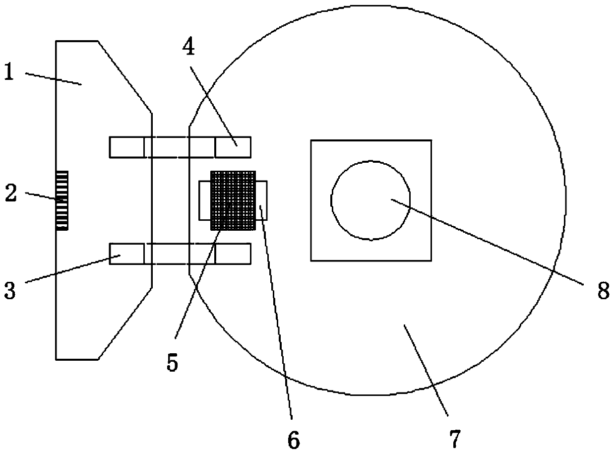
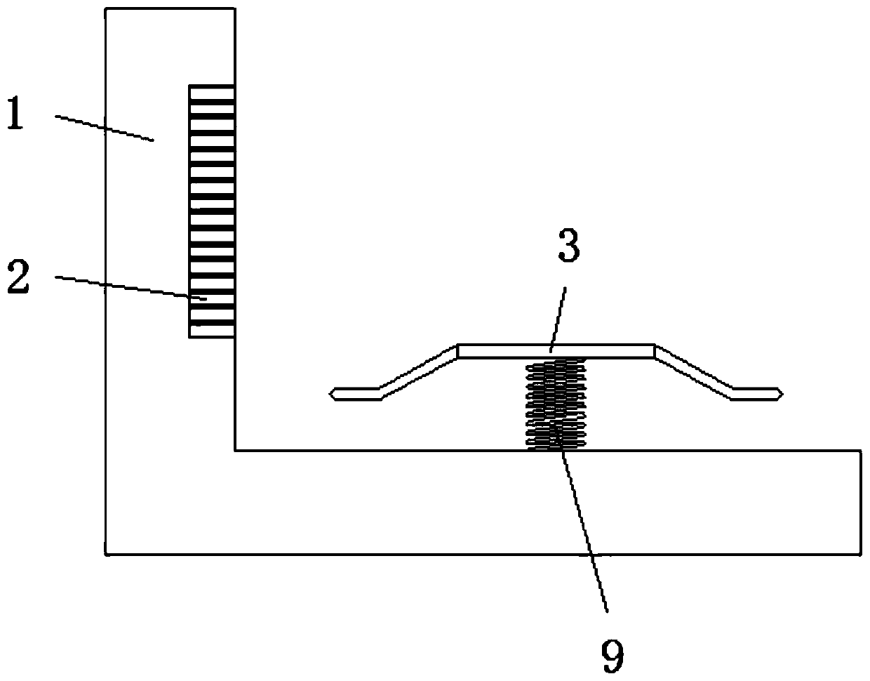
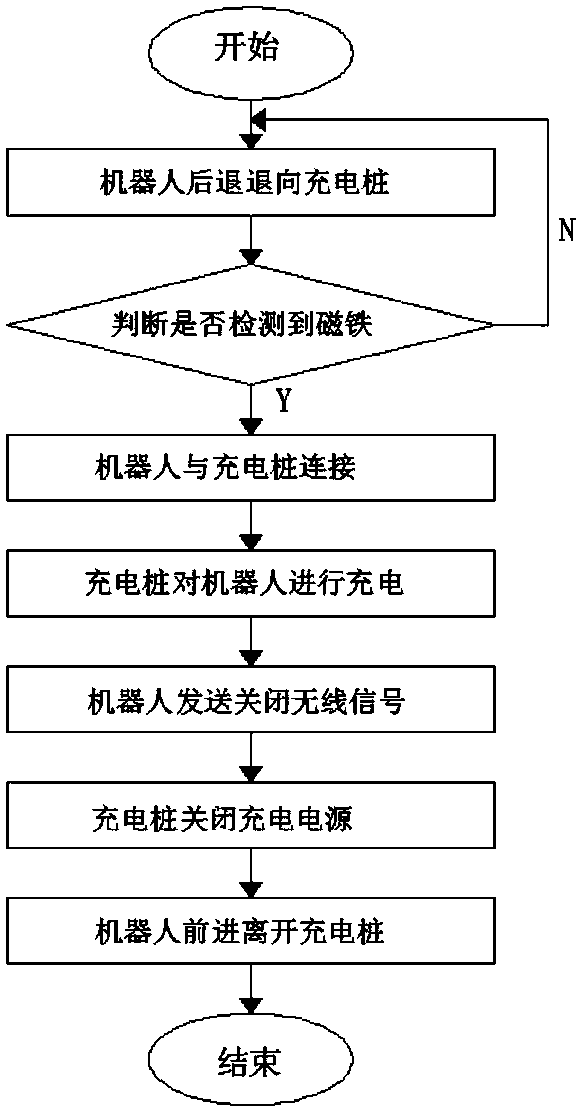
[0048] like Figure 1-Figure 3 As shown, a robot automatic charging system includes: a charging pile 1 and a robot 7;

[0049] The vertical section of the charging pile 1 is an L-shaped structure;

[0050] The outer wall of the horizontal end of the charging pile 1 is provided with an electrode sheet spring 11, and the top of the electrode sheet spring 11 is elastically connected to the charging pile electrode sheet 3;

[0051] When the electrode sheet 3 of the charging pile is squeezed by external force, the electrode sheet spring 11 will be compressed and deformed by the force, so that the electrode sheet 3 of the charging pile will move down and make it contact w...


PUM


Abstract

The invention discloses a robot automatic charging system, comprising: a charging pile and a robot, wherein the vertical section of the charging pile is in an L shape; the outer wall of the horizontalend of the charging pile is provided with an electrode piece spring; a charging pile electrode piece is elastically connected the top of the electrode piece spring; a control main board is disposed inside the robot; and a robot electrode piece is disposed on the tail of the robot. In the present invention, the robot automatic charging system uses a charging method in which charging is performed before contact, thereby avoiding electric sparks caused by the friction of the electrode pieces in an energized state, ensuring the charging safety of the charging pile, and greatly improving the charging safety of the robot. Further, the robot automatic charging system uses a noncontact induction method to ensure the sufficient safety of the distance between the robot and the charging pile, avoidthe wear caused by the mechanical triggering mode of a contact micro switch, and avoid damage to both the robot and the charging pile caused by direct collision of the robot and the charging pile.

Description

technical field [0001] The invention relates to the technical field of robot charging, in particular to an automatic robot charging system. Background technique [0002] A robot is a machine device that automatically performs work. It can accept human commands, run pre-programmed programs, and act according to principles and programs formulated with artificial intelligence technology. Its task is to assist or replace human work. After the rechargeable service robot works, it is necessary to charge the service robot in time to ensure that the service robot can continue to carry out follow-up work. [0003] Existing service robots usually use a contact charging method, that is, the charging electrode is installed at the bottom, and the electrode on the charging pile is always powered. During the automatic charging process, once the electrode on the robot is detected When there is electricity, it means that the robot will start charging when it is in contact with the charging ...

Claims


Application Information

Patent Timeline
IPC IPC(8): H02J7/00
CPCH02J7/0029H02J7/0042
Inventor 孙斌
Owner HANGZHOU AMY RONOTICS CO LTD
Learn More