Clutch riveting auxiliary device

An auxiliary device and clutch technology, applied in the field of auto parts assembly, can solve problems such as safety hazards, slow efficiency, complex clutch assembly, etc., and achieve the effect of smooth rotation

Active Publication Date: 2020-01-17
ANHUI TECHN COLLEGE OF MECHANICAL & ELECTRICAL ENG
View PDF5 Cites 8 Cited by
  • Summary
  • Abstract
  • Description
  • Claims
  • Application Information

AI Technical Summary

Problems solved by technology

[0003] The assembly of the clutch is relatively complicated. One of the structures is riveted by a pressure plate and two friction plates. The two friction plates are respectively located on both sides of the pressure plate, and the pressure plate is erected between them; the equipment used is Riveting machine, riveting machine is a very common assembly machine. The aforementioned structural assembly is now manually loaded. Specifically, the pressure plate is first placed on the processing table, and then a piece of friction plate is placed on the pressure plate. surface, and then manually turn the former step by step to realize the circumferential riveting work, then turn the former over so that the original surface of the pressure plate is facing upwards, then put in the next piece of friction plate, and then continue to the previous step Operation of riveting, due to the slow efficiency of manual feeding, turning over and rotating the material, and the cost of employment is also high, and there are certain safety hazards in frequent manual operations

Method used


Image

  • Clutch riveting auxiliary device
  • Clutch riveting auxiliary device
  • Clutch riveting auxiliary device

Examples


Embodiment Construction

[0034] A number of embodiments of the present invention will be disclosed in the following figures. For the sake of clarity, many practical details will be described together in the following description. It should be understood, however, that these practical details should not be used to limit the invention. That is, in some embodiments of the invention, these practical details are not necessary. In addition, for the sake of simplifying the drawings, some well-known and commonly used structures and components will be shown in a simple schematic manner in the drawings.

[0035]In addition, in the present invention, descriptions such as "first", "second" and so on are used for description purposes only, and do not refer to the meaning of order or sequence, nor are they used to limit the present invention, but are only for the purpose of distinguishing the following The components or operations described by the same technical terms are only used, but should not be understood as...


PUM


Abstract

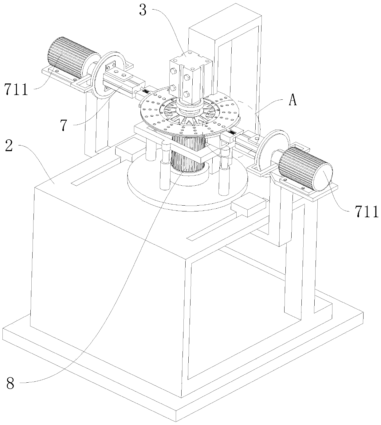
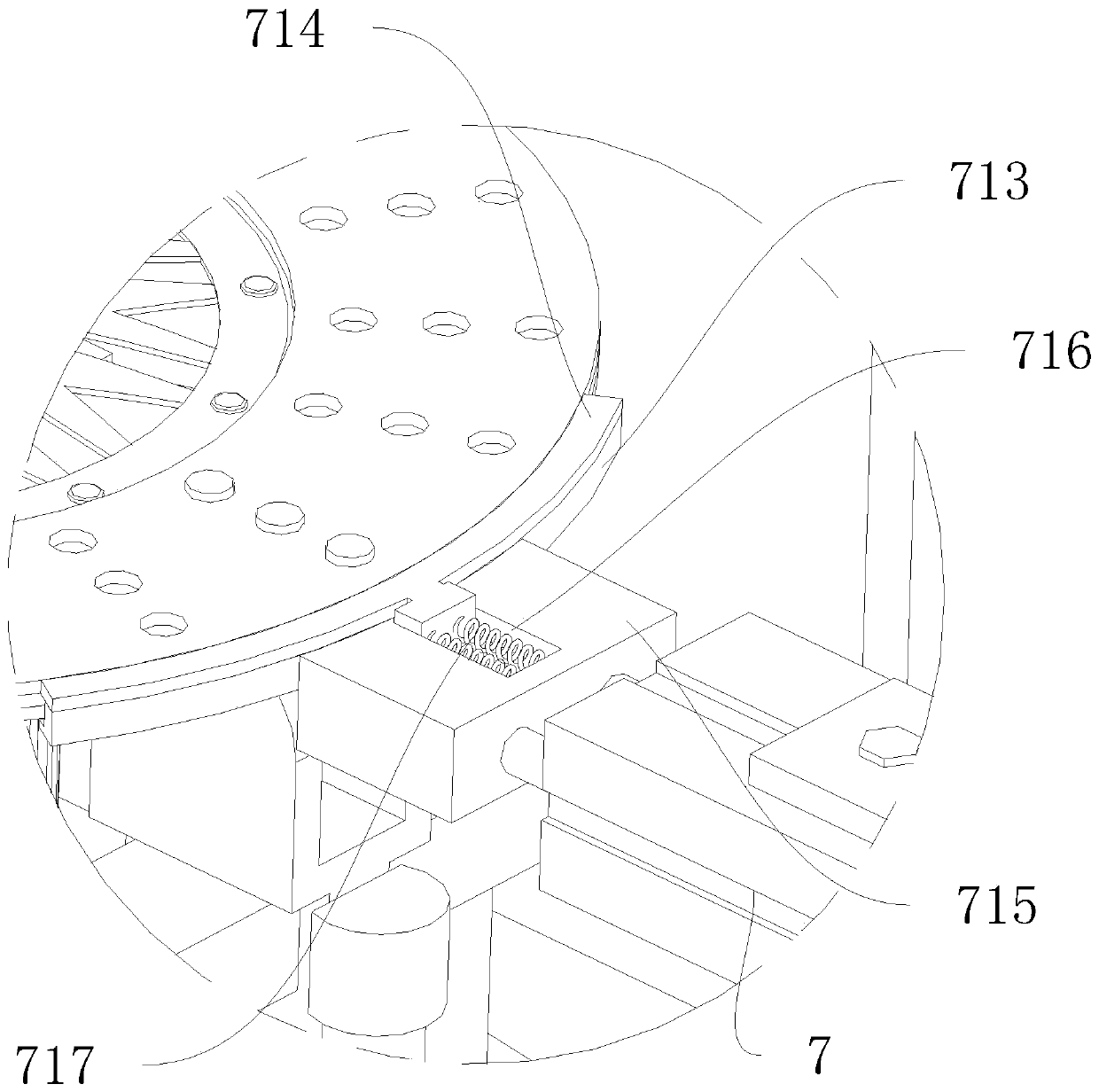
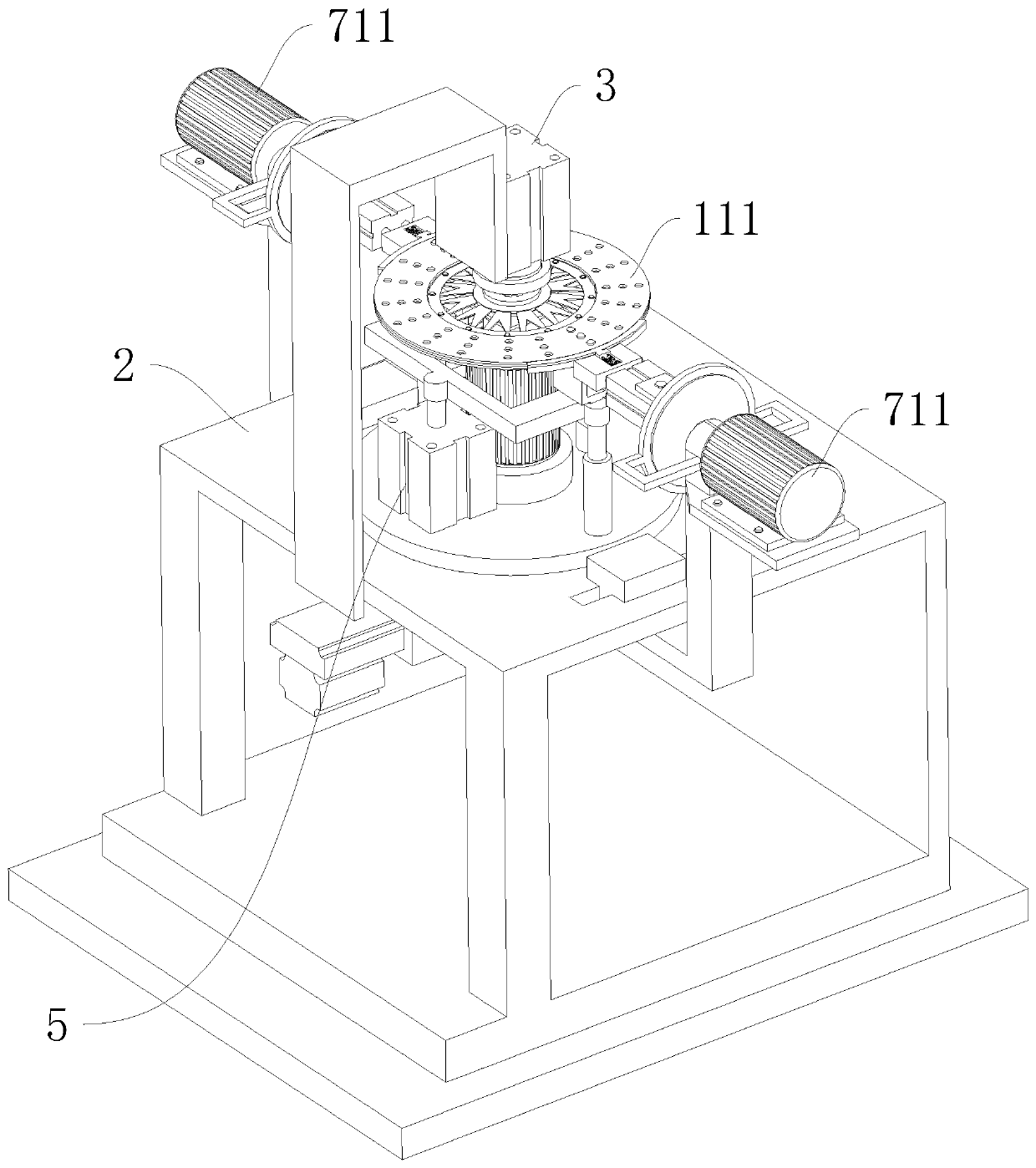
The invention relates to the technical field of automobile component assembling, in particular to a clutch riveting auxiliary device. The clutch riveting auxiliary device includes a processing table,and further includes a guide mechanism, a centering post and a servo motor. The guide mechanism is arranged above the processing table in an inverse manner, the servo motor is arranged below the guidemechanism, a main shaft of the servo motor is provided with a fixed shaft, the centering post can be inserted into the fixed shaft in a vertical movement manner, the guide end of the guide mechanismis provided with a press-fitting structure which is in inserting-connection fit with the upper end of the centering post, and the exterior of the centering post is provided with a lifting mechanism intransmission connection with the centering post. A second supporting frame is arranged below the processing table, the two ends of the second supporting frame are vertically upward, the two ends areeach provided with a clamping cylinder, and the back of each clamping cylinder is provided with an overturning motor in transmission connection to the clamping cylinder. A displacement mechanism is also arranged at the bottom of the processing table, and the second supporting frame is in transmission connection to the displacement mechanism. The clutch riveting auxiliary device can greatly reducemanual operation, improves the production efficiency and reduces safety incidents.

Description

technical field [0001] The invention relates to the technical field of assembly of automobile parts, in particular to a clutch riveting auxiliary device. Background technique [0002] The assembly and adjustment of the clutch is an important part of the maintenance process, and the correctness of the assembly directly affects the normal operation of the clutch. Generally, the assembly sequence of the clutch is to assemble the clutch pressure plate assembly first, then install the assembly and the driven plate on the rear end surface of the flywheel, and finally install the operating mechanism. [0003] The assembly of the clutch is relatively complicated. One of the structures is riveted by a pressure plate and two friction plates. The two friction plates are respectively located on both sides of the pressure plate, and the pressure plate is erected between them; the equipment used is Riveting machine, riveting machine is a very common assembly machine. The aforementioned s...

Claims


Application Information

Patent Timeline
Patent Type & Authority Applications(China)
IPC IPC(8): B21J15/38B21J15/32B21J15/42
CPCB21J15/38B21J15/32B21J15/42
Inventor 李庆赵文英吴亚兰陈露王志伟朱稚华王凯
Owner ANHUI TECHN COLLEGE OF MECHANICAL & ELECTRICAL ENG
Why Eureka
Try Eureka