CCD automatic positioning die cutting machine

An automatic positioning and die-cutting machine technology, applied in metal processing and other directions, can solve the problems of affecting die-cutting efficiency, taking a long time, and failing to meet the accuracy requirements, so as to improve die-cutting accuracy, die-cutting efficiency, and die-cutting. The effect of higher precision and die-cutting efficiency, higher die-cutting precision and die-cutting efficiency

Pending Publication Date: 2020-01-17
GUANGDONG FXD INTELLIGENT EQUIP CO LTD
View PDF0 Cites 13 Cited by
  • Summary
  • Abstract
  • Description
  • Claims
  • Application Information

AI Technical Summary

Problems solved by technology

[0003] Existing CCD die-cutting machines usually use a CCD camera to position the material on the lower die base, and then use the knife die on the upper die base to punch downwards for die-cutting. When the material is mobile phone frame paper, the material needs to be cut. Die-cut according to the size requirements and mount it on the mobile phone, so the requirements for die-cutting accuracy are very high. If the frame paper does not meet the requirements after die-cutting, it will directly affect the placement effect of the mobile phone, and the responsibility for die-cutting to meet the required accuracy Drop directly onto the CCD die-cutting machine
The existing die-cutting machine cannot be adjusted in the horizontal direction. If the material is misplaced, it needs to be stopped to adjust the position of the material. Die-cutting can only be performed after the material is aligned. After die-cutting, it will inevitably fail to meet the precision requirements, and it will take a long time to adjust the shutdown, thus affecting the efficiency of die-cutting

Method used


Image

  • CCD automatic positioning die cutting machine
  • CCD automatic positioning die cutting machine
  • CCD automatic positioning die cutting machine

Examples


Embodiment

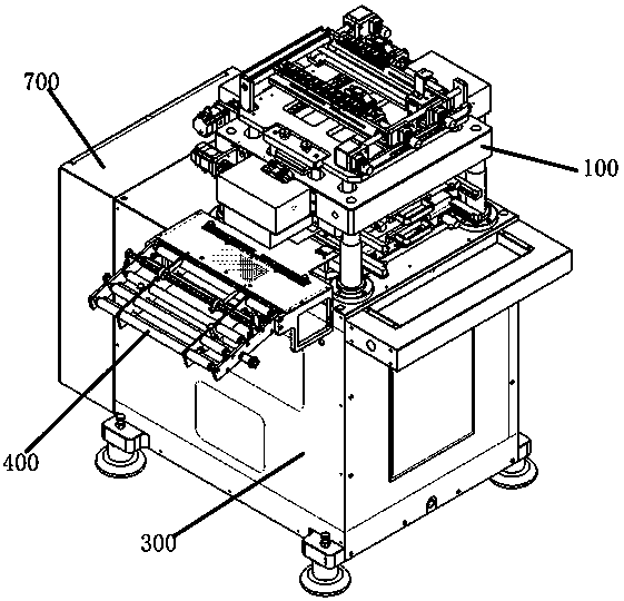
[0044] Please refer to the attached Figures 1 to 22 , the present invention provides a CCD automatic positioning die-cutting machine, including a die-cutting host 300 for providing stamping power, a control box 700 for centralized control, a feeding mechanism 400 for material feeding, and a die-cutting The positioning adjustment mechanism 100 for horizontal adjustment and automatic positioning, the control box 700 is installed behind the die-cutting host 300, the adjustment mechanism 100 is installed on the die-cutting host 300, and the feeding mechanism 400 is installed on the die-cutting host 300. The side of the die-cutting host 300 is described.

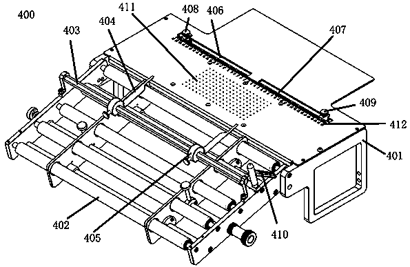
[0045] Specifically, please refer to image 3 , the feeding mechanism 400 includes a feeding frame 401, a drum 402, a width adjustment frame 403, a left adjustment limit arm 404, a right adjustment limit arm 405, a left width measurement slot 406, a left measurement adjustment block 408, a right width measurement Groove 407, r...


PUM


Abstract

The invention provides a CCD automatic positioning die cutting machine, and belongs to the field of die cutting equipment. The CCD automatic positioning die cutting machine comprises a die cutting main machine for providing stamping power, a control box for centralized control, a feeding mechanism for feeding materials and a positioning adjusting mechanism for die cutting horizontal adjusting automatic positioning. The control box is mounted behind the die cutting main machine, the adjusting mechanism is mounted on the die cutting main machine, and the feeding mechanism is mounted on the sideportion of the die cutting main machine. Compared with the prior art, adjusting in the horizontal direction can be carried out under the condition without halts, meanwhile, the die cutting precision and the die cutting efficiency are improved, it is not needed to worry about the situation that the die cutting position is wrong due to material staggering, and the CCD automatic positioning die cutting machine has the beneficial effects that the die cutting precision and the die cutting efficiency are higher.

Description

technical field [0001] The invention belongs to the field of die-cutting equipment, and in particular relates to a CCD automatic positioning die-cutting machine. Background technique [0002] Die Cutting Machine (Die Cutting Machine), also known as beer machine, cutting machine, CNC stamping machine, is mainly used for die cutting of some corresponding non-metallic materials, self-adhesive, EVA, double-sided adhesive tape, electronics, mobile phone rubber pads, etc. (full break, half break), indentation and bronzing operations, lamination, automatic waste discharge, die-cutting machines use steel knives, metal molds, steel wires (or templates carved from steel plates), and apply certain pressure through the embossing plate It is an important equipment for post-press packaging processing to cut printed matter or cardboard into a certain shape. [0003] Existing CCD die-cutting machines usually use a CCD camera to position the material on the lower die base, and then use the ...

Claims


Application Information

Patent Timeline
Patent Type & Authority Applications(China)
IPC IPC(8): B26F1/38B26F1/44B26D5/20B26D7/26
CPCB26D5/20B26D7/2628B26F1/38B26F1/44
Inventor 侯立新戴军生
Owner GUANGDONG FXD INTELLIGENT EQUIP CO LTD
Why Eureka
Try Eureka