
Electric air compressor start-stop system and method for new energy vehicle

A technology for electric air compressors and new energy vehicles, which is applied in the direction of vehicle components, pump/compressor arrangement, brakes, etc., and can solve the mismatch of the unloading relationship of the dryer 2, the inability of the dryer 2 to unload and regenerate, and the system Pressure rise and other problems, to achieve the effect of easy promotion, simple structure, and priority of gas supply

Pending Publication Date: 2020-01-17
XUZHOU XUGONG AUTOMOBILE MFG CO LTD
View PDF9 Cites 4 Cited by
  • Summary
  • Abstract
  • Description
  • Claims
  • Application Information

AI Technical Summary

Problems solved by technology

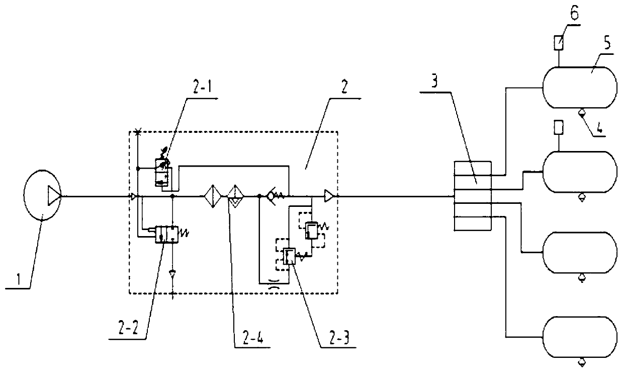
For the start and stop principle of traditional air compressors, see figure 1 , the start-stop signal of the air compressor 1 comes from the air pressure sensor 6 connected to the air storage tank 5. Since the air pressure sensor 6 has a large tolerance range for the detection pressure of the air storage tank 5, the opening value of the mechanical pressure regulating valve 2-1 It is also a large tolerance range, which will cause a mismatch between the shutdown of air compressor 1 and the unloading relationship of dryer 2: if the shutdown pressure of air compressor 1 is lower than the opening pressure of mechanical pressure regulating valve 2-1, the air Compressor 1 will stop first, the system pressure cannot be further increased, mechanical pressure regulating valve 2-1 cannot be opened, and dryer 2 cannot be unloaded and regenerated; if the shutdown pressure of air compressor 1 is higher than that of mechanical pressure regulating valve 2- The opening pressure of 1, the mechanical pressure regulating valve 2-1 is opened first, the dryer 2 is unloaded, and the system pressure cannot be further increased, causing the air compressor to work all the time

Method used


Image

  • Electric air compressor start-stop system and method for new energy vehicle
  • Electric air compressor start-stop system and method for new energy vehicle
  • Electric air compressor start-stop system and method for new energy vehicle

Examples


Embodiment Construction

[0023] In order to make the objectives, technical solutions, and advantages of the present invention clearer, the present invention will be described in further detail below. However, it should be understood that the specific embodiments described here are only used to explain the present invention, and are not used to limit the scope of the present invention.

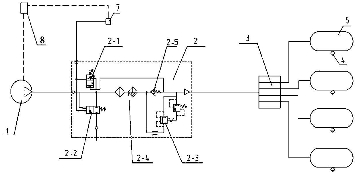
[0024] Such as figure 2 As shown, a start-stop system for an electric air compressor for a new energy vehicle includes an air compressor 1, a dryer 2, a four-circuit protection valve 3, and an air reservoir 5. The air reservoir 5 is equipped with a drain valve 4, and the air The compressor 1, the dryer 2, the four-circuit protection valve 3, and the gas storage cylinder 5 are connected in sequence to form a control pipeline, and also include a pressure detection device 7 and a controller 8;

[0025] The dryer 2 includes a mechanical pressure regulating valve 2-1, an exhaust valve 2-2, a return valve 2-3, a filter screen 2-...


PUM


Abstract

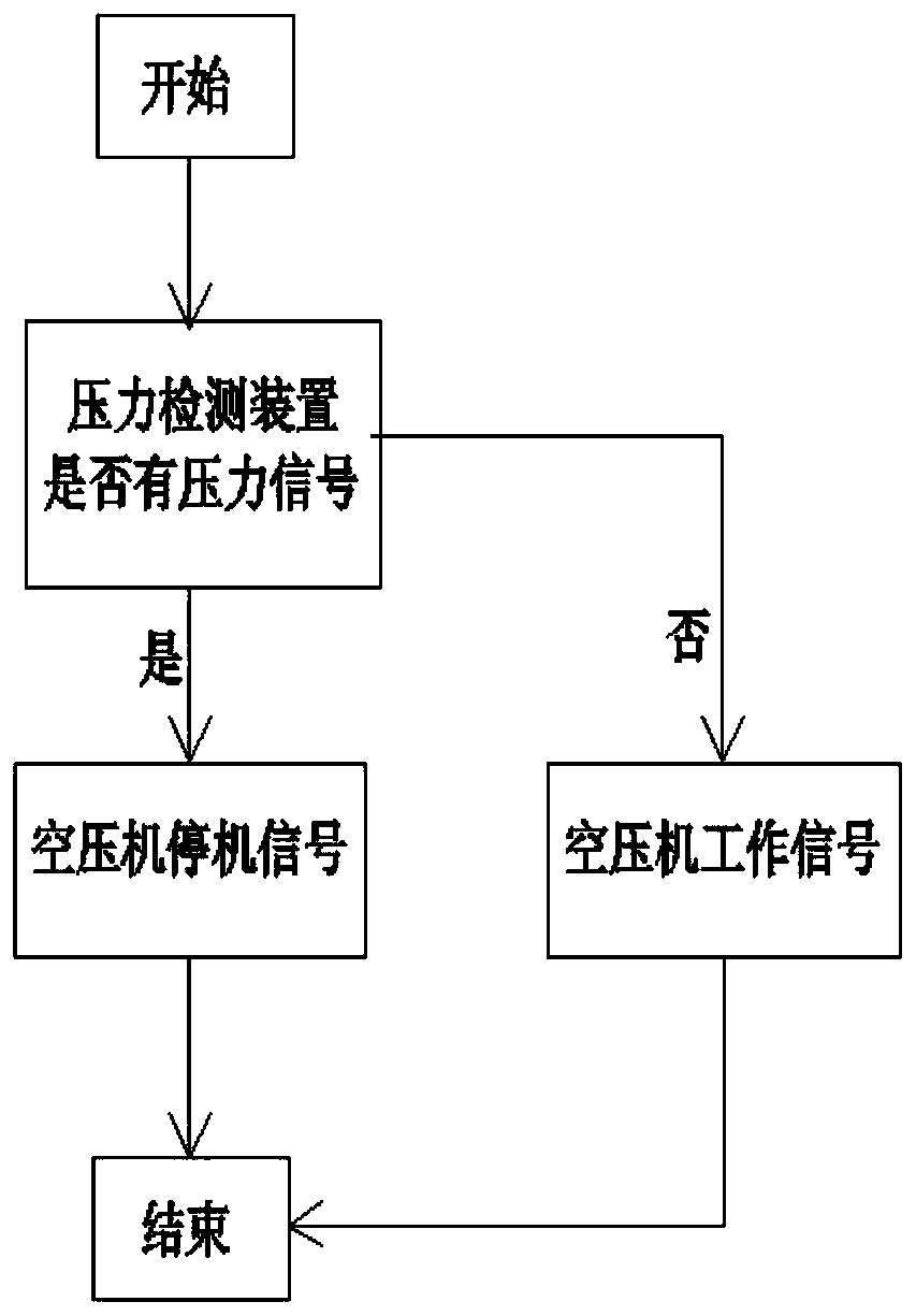
The invention discloses an electric air compressor start-stop system for a new energy vehicle. The system comprises an air compressor, a dryer, a four-loop protection valve and an air cylinder which are orderly connected to form a control pipeline, and also comprises a pressure detection device and a controller. The dryer comprises a mechanical pressure regulating valve, an exhaust valve, a returnvalve, a filter sieve and a one-way valve, the filter sieve and the one-way valve are respectively arranged on a control pipeline between the air compressor and the four-loop protection valve, and anexhaust branch formed by connecting the mechanical pressure regulating valve and the exhaust valve is connected with a pipeline of the filter sieve and the one-way valve in parallel. A return branchwhere the return valve is located is connected with a pipeline of the one-way valve in parallel, one end of the pressure detection device is connected to a pipeline between the mechanical pressure regulating valve and the exhaust valve, and the other end of the pressure detection device is connected with the controller. The pressure detection device is used for monitoring the pressure of the pipeline between the mechanical pressure regulating valve and the exhaust valve and transmitting a monitored pressure signal to the controller, and the controller is connected with the air compressor. Theelectric air compressor start-stop system not only can realize normal work of the dryer, but also can realize the start and stop of the air compressor.

Description

Technical field [0001] The invention relates to a start-stop system and a start-stop method for an electric air compressor for a new energy vehicle, and belongs to the technical field of automobile electrical appliances. Background technique [0002] The structure of the dryer of the traditional air brake fuel vehicle is as figure 1 , The compressed air generated by the air compressor 1 passes through the dryer 2 and the four-circuit protection valve 3 and enters the air storage cylinder 5. The mechanical pressure regulating valve 2-1 is used to adjust the system pressure. When the pressure in the air storage cylinder 5 reaches the system set pressure, the mechanical pressure regulating valve 2-1 opens, and the compressed air in the air storage cylinder 5 flows through the mechanical pressure regulating valve 2- 1 reaches the exhaust valve 2-2, so that the exhaust valve 2-2 is opened. At this time, the compressed air generated by the air compressor 1 will be discharged through th...

Claims


Application Information

Patent Timeline
Patent Type & Authority Applications(China)
IPC IPC(8): B60T17/00B60T17/02
CPCB60T17/004B60T17/02
Inventor 任显国高嵩史钊宇王赛李广霍电辉刘安李少文杜科锦
Owner XUZHOU XUGONG AUTOMOBILE MFG CO LTD
Learn More