
Mode Switching Control Method for Power Split Hybrid Power System Based on State Estimation

A Hybrid System, Hybrid Mode Technology

Active Publication Date: 2021-09-03
TONGJI UNIV
View PDF9 Cites 0 Cited by
  • Summary
  • Abstract
  • Description
  • Claims
  • Application Information

AI Technical Summary

Problems solved by technology

During this process, due to the influence of the reverse drag torque of the engine and the differences in the characteristics of different power components, the torque at the power output end of the gearbox may fluctuate greatly, which will lead to prominent problems in the vehicle's power and driving comfort.
[0003] In the prior art, there are few studies on the mode switching process control of the power-split hybrid power system. In practical applications, traditional rule-based and empirical logic gate-limited switching control strategies are mostly used. greater limitations
Prior art CN107351837A discloses a mode switching method of a power split hybrid power system. Aiming at the pure electric to hybrid mode switching process of a power split hybrid power system, a control method combining offline optimal control and online model predictive control rolling optimization is proposed. However, the model predictive control of this method does not consider the limits of the engine speed, motor torque and its rate of change in the actual system, and does not combine and utilize the estimated information of the gearbox input shaft and power output torque.

Method used


Image

  • Mode Switching Control Method for Power Split Hybrid Power System Based on State Estimation
  • Mode Switching Control Method for Power Split Hybrid Power System Based on State Estimation
  • Mode Switching Control Method for Power Split Hybrid Power System Based on State Estimation

Examples


Embodiment Construction

[0023] The present invention will be described in detail below in conjunction with the accompanying drawings and specific embodiments. This embodiment is carried out on the premise of the technical solution of the present invention, and detailed implementation and specific operation process are given, but the protection scope of the present invention is not limited to the following embodiments.

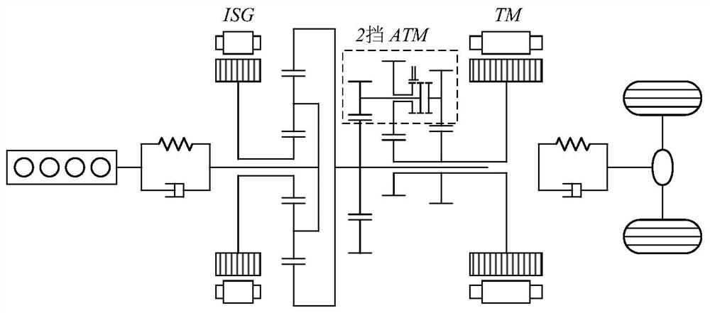
[0024] Such as figure 1 As shown, the power-split hybrid system includes an engine, a motor ISG, a motor TM, a power coupling device with a planetary row structure, and a two-speed AMT gearbox. The engine is connected to the planetary row through a torsional damper, the ISG motor is connected to the sun gear, the ring gear is connected to the output shaft, and the TM motor is connected to the output shaft through a two-speed AMT gearbox. Through different combinations of the working states of each power source, the hybrid system has four main working modes: pure electric first gear a...


PUM


Abstract

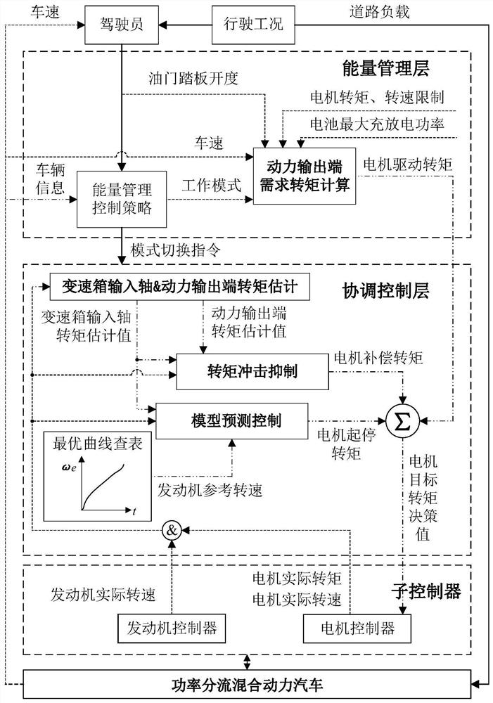
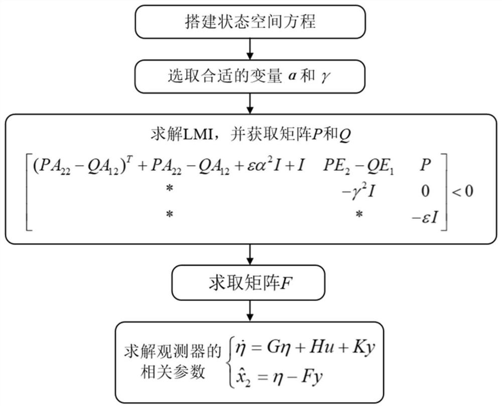
The present invention relates to a mode switching control method of a power-split hybrid power system based on state estimation. Aiming at switching between pure electric and hybrid power modes of a power-split hybrid power system, the steps are as follows: S1: In the energy management layer, based on the demand torque calculation at the power output end, the calculation satisfies The motor drive torque required by the vehicle's power requirements; S2: Design an unknown input observer at the coordination control layer to estimate the gearbox input shaft and power output torque online; S3: Based on the estimated value of the gearbox input shaft torque, design a model prediction The control strategy realizes the smooth start and stop of the engine and solves the start-stop torque of the motor; S4: Designs a torque shock suppression strategy based on the estimated value of the torque at the power output end and solves the compensation torque of the motor; S5: Drives the above motor, starts and stops, and compensates The torque is superimposed to obtain the motor target torque decision value. Compared with the prior art, the present invention has the advantages of improving the driving comfort of the whole vehicle during the mode switching process of the power split hybrid power system, and taking into account the starting and stopping performance of the engine.

Description

technical field [0001] The invention relates to a mode switching control method of a power split hybrid power system, in particular to a state estimation-based pure electric and hybrid power mode switching control method. Background technique [0002] The power split hybrid system is the mainstream technical solution for deep and plug-in hybrid electric vehicles. It uses the power split device of the planetary row and two motors to realize the decoupling of the engine working state from the wheel speed and the required torque. Reasonable switching between modes ensures that the engine and motor always work in the high-efficiency range, thereby maximizing the energy economy and emission of the vehicle. However, when the system switches between pure electric mode and hybrid mode, it is accompanied by a rapid start and stop of the engine. During this process, due to the influence of the reverse drag torque of the engine and the differences in the characteristics of different p...

Claims


Application Information

Patent Timeline
Patent Type & Authority Patents(China)
IPC IPC(8): B60W20/11B60W10/06B60W10/08B60W30/182
CPCB60W10/06B60W10/08B60W30/182B60W2510/0638B60W2510/081B60W2510/083B60W2520/10B60W2540/10B60W2710/06B60W2710/083B60W20/11Y02T10/62
Inventor 赵治国李蒙娜
Owner TONGJI UNIV
Learn More