Two-stage gravity separation device for oil-containing wastewater treatment, and treatment process

A technology of gravity separation and wastewater treatment, applied in water/sewage multi-stage treatment, water/sludge/sewage treatment, grease/oily substance/float removal device, etc. The problems of high intensity and labor intensity can achieve the effect of short residence time, increased oil-water separation efficiency, and small equipment footprint.

Pending Publication Date: 2020-01-17
北京飞燕石化环保科技发展有限公司
1 Cites 1 Cited by

AI-Extracted Technical Summary

Problems solved by technology

At present, the method of removing oil from kitchen waste sewage generally adopts the method of grease trap, and its main disadvantages are large area, high labor intensity, and poor decontamination ...

Method used

According to the shallow pond principle of Hazhen, the spacing between the corrugated plates is relatively small, and the oil droplet particle size range of the oil phase to be separated can be greatly promoted, that is, the small particle size oil droplet with a slower floating speed in the common gravity field enters The shallow flow channel between the corrugated plates also has better floating ability; in addition, the alternate expansion and contraction of the cross-section in the corrugated plates improves the collision efficiency of small-sized oil droplets, and then coalesces to form large-sized oil droplets. drops to achieve the purpose of increasing the separation efficiency. Since the oil phase will converge in the raised part of the corrugated plate, the floating of the converging oil phase can be promoted by adjusting the horizontal angle of the corrugated plate, so preferably, the plurality of first corrugated plates and the plurality of second corrugated plates The corrugated plates are all inclined upwards along the direction from front to back. Further preferably, the angles between the horizontal planes of the plurality of first corrugated plates can be 50°-70°, preferably, the angles are 60°. Since the oil concentration in the waste water in the secondary separation area has been greatly reduced, the horizontal angl...

Abstract

The invention discloses a two-stage gravity separation device for oil-containing wastewater treatment. The two-stage gravity separation device comprises a closed box body, wherein the bottom plate ofthe box body comprises a horizontal bottom plate and a first inclined plate, the horizontal bottom plate and the first inclined plate are sequentially connected from front to back, a second inclined plate is arranged in the box body, inclines upwards along the height direction from front to back, and divides the internal space of the box body into a first-stage treatment cavity and a second-stagetreatment cavity, the first-stage treatment cavity and the second-stage treatment cavity are not communicated to each other, a first corrugated plate group and a first oil separation and water passingassembly are arranged in the first-stage treatment cavity, and a second corrugated plate group and a second oil separation and water passing assembly are arranged in the second-stage treatment cavity. The invention further discloses a treatment process adopting the device. According to the invention, the device has the beneficial effects of short residence time, small occupation area, strong adaptability to raw water fluctuation, closed equipment body, no moving part in the equipment main body, simple structure, stable operation effect and low equipment cost.

Application Domain

Technology Topic

Gravity separationRaw water +9

Image

  • Two-stage gravity separation device for oil-containing wastewater treatment, and treatment process
  • Two-stage gravity separation device for oil-containing wastewater treatment, and treatment process

Examples

  • Experimental program(1)

Example Embodiment

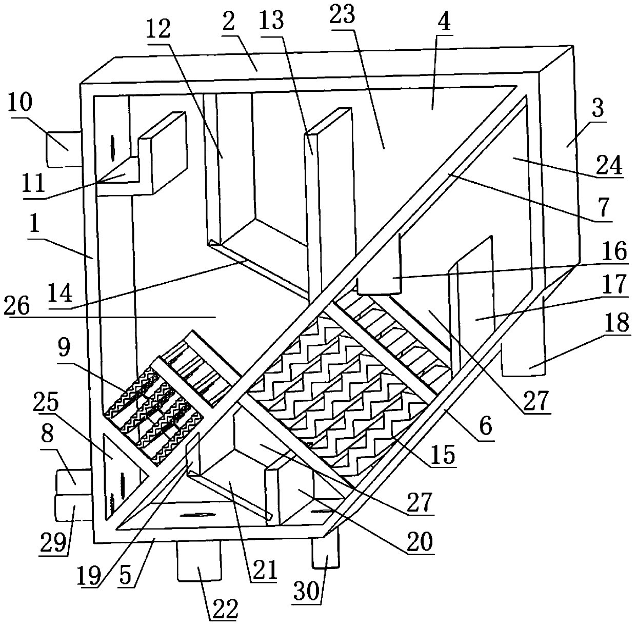
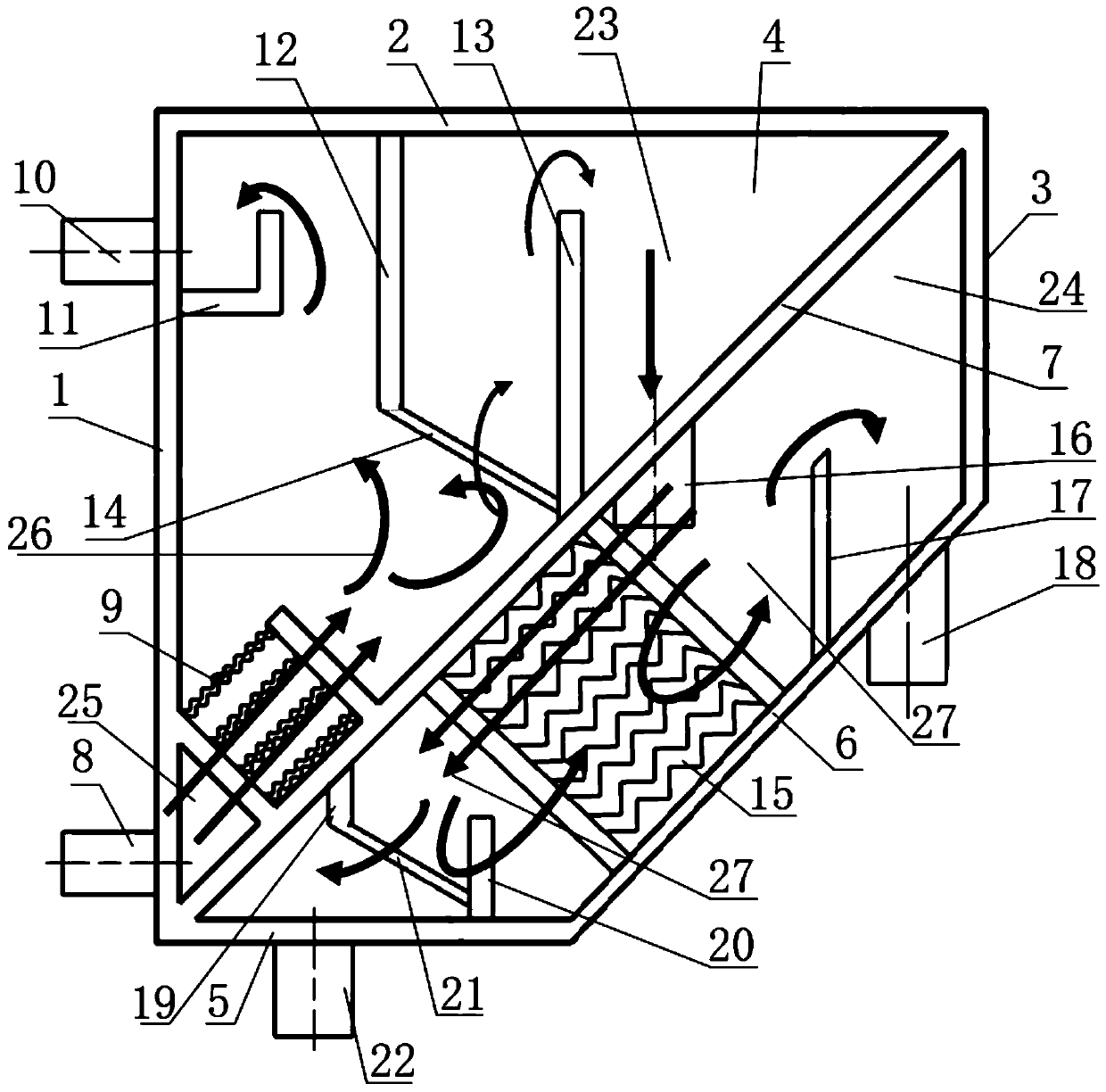
[0030] The present invention will be further described below in conjunction with the drawings:
[0031] Such as figure 1 As shown, a two-stage gravity separation device for oily wastewater treatment includes a closed box body. The box body is composed of a bottom plate, a front side wall 1, a top plate 2, a rear side wall 3, a left side wall 4 and a right side wall (in the figure) Not shown, figure 1 It is a schematic diagram of the structure after removing the right side wall). The bottom plate of the box body is composed of a horizontal bottom plate 5 and a first sloping plate 6 that are sequentially connected from front to back. The rear direction is inclined upward, and the inside of the box body is provided with a second inclined plate 7 which is inclined upward in a height from front to rear direction. The second inclined plate 7 divides the internal space of the box body into an unconnected one. The first-level processing chamber 23 and the second-level processing chamber 24, the first-level processing chamber is located at the upper part of the second-level processing chamber,
[0032] The bottom of the front side wall 1 of the box body is provided with a waste water inlet 8 connected to the primary treatment chamber 23. The primary treatment chamber 23 is provided with a first corrugated plate group 9 which combines one The first-stage processing chamber is divided into a first front chamber 25 and a first rear chamber 26. The first corrugated plate includes a plurality of first corrugated plates, the plurality of first corrugated plates are parallel or substantially parallel to each other, and the first front chamber 25 and the first rear side cavity 26 are communicated by a channel formed between adjacent first corrugated plates. The top of the front side wall 1 of the box body is provided with a primary oil outlet 10, and the top of the inner wall of the front side wall 1 of the box body is provided with The first-level oil outlet weir 11 matched with the first-level oil outlet 10, the first rear cavity 26 is sequentially provided with a first baffle 12 and a first-level water outlet weir 13 along the front to back direction. The corresponding edges of the plate 12 are respectively connected with the top plate 2, the left side wall 4 and the right side wall of the box body, and the corresponding edges of the primary water outlet weir plate 13 are respectively connected with the second inclined plate 7, the left side wall 4 and the right side wall , The first baffle 12 and the primary water outlet weir 13 and between the primary water outlet weir 13 and the top plate 2 form a channel for waste water to pass through, the first baffle 12 and the primary water outlet weir 13 A first oil-separating and water-passing component 14 is arranged between the lower ends, and the top of the primary oil outlet weir 11 and the primary water outlet weir 11 have the same height to keep the liquid level consistent;
[0033] A second corrugated plate group 15 is provided in the secondary processing chamber 24. The second corrugated plate group 15 divides the secondary processing chamber into a second front side cavity 27 and a second rear side cavity 28. The second corrugated plate group includes a plurality of The second corrugated plate, the plurality of second corrugated plates are parallel or substantially parallel to each other, the second front side cavity 27 and the second rear side cavity 28 are communicated by a channel formed between adjacent second corrugated plates, and the second inclined plate 7 A primary water outlet 16 connected to the second rear cavity 28 is provided at a position behind the primary water outlet weir plate 13, and
[0034] The first sloping plate 6 is provided with a secondary oil outlet weir at the position behind the primary water outlet 16, and the first sloping plate 6 is provided with a secondary oil outlet 18 at the position behind the secondary oil outlet weir. A second baffle 19 and a purified water outlet weir are arranged in the second front cavity 27 in order from front to back. The corresponding edges of the second baffle 19 are respectively connected to the second inclined plate 7, the left side wall 4 and the right side. The side walls are connected, and the corresponding edges of the purified water outlet weir are respectively connected to the horizontal bottom plate 5, the left side wall 4 and the right side wall. The second baffle 19 and the purified water outlet weir form a channel for waste water to pass through. A second oil-cut and water-passing component 21 is provided between the lower end of the baffle 19 and the lower end of the purified water outlet weir. The horizontal bottom plate 5 is located at the front side of the second oil-cutting and water-passing component 21 with a purified water outlet 22.
[0035] The use of corrugated plates increases the separation efficiency of the oil and water phases in the gravitational field and shortens the residence time of the equipment; in addition, the oil-separating and water-passing components increase the oil-water separation efficiency while further improving the phase distribution of the oil and water phases in the equipment , So that the internal flow field of the equipment is more suitable for the separation of oil and water. Finally, through a two-stage oil-water separation process in a box, the equipment is compact, efficient, and airtight.
[0036] Preferably, both the first purification component and the second purification component are arranged obliquely downward in a direction from front to back. Further preferably, the included angle between the first purification component and the horizontal plane may be 30°-60° to prevent the formation of a dead zone. Preferably, the included angle is 45°. In the same way, the included angle between the second purification component and the horizontal plane may be 20°-60°, and preferably, the included angle is 30°.
[0037] Preferably, the multiple first corrugated plates, the first-level oil outlet weir 11, the first baffle 12, the first-level water outlet weir 13, the first oil-separating and water-passing component 14, the second-level oil outlet weir , The second corrugated plate, the second baffle 19, the purified water outlet weir plate and the second oil-separating and water-passing component 21 are all perpendicular to the left side wall 4 or the right side wall, and the corresponding edges are all aligned with the left side wall 4 or the right side Wall connection.
[0038] According to the principle of Hazhen Shallow Pool, the distance between the corrugated plates is small, which can greatly increase the particle size range of the oil droplets in the oil phase to be separated, that is, the small-sized oil droplets that float slowly in the ordinary gravity field enter the corrugated plates. The shallow flow channel also has better floating ability; in addition, the alternating expansion and contraction of the cross-section in the corrugated plate increases the collision efficiency of small-size oil droplets, and then coalesces to form large-size oil droplets. The purpose of increasing separation efficiency. Since the oil phase will converge on the convex part of the corrugated plate, the horizontal angle of the corrugated plate can be adjusted to improve the floating of the concentrated oil phase. Therefore, preferably, the plurality of first corrugated plates and the plurality of second corrugated plates The corrugated plates are all inclined upwardly from front to back. Further preferably, the included angle of the horizontal planes of the plurality of first corrugated plates may be 50° to 70°, and preferably, the included angle is 60°. Since the oil concentration in the wastewater in the secondary separation zone has been greatly reduced, the horizontal included angle of the second corrugated board should be flatter to prevent the wastewater from falling too fast and taking too much oil phase that cannot be raised. The included angle between the two corrugated plates and the horizontal plane is both 20°-50°, preferably, the included angle is 45°.
[0039] Preferably, the first-level oil outlet weir 11 is composed of a horizontal plate and a vertical plate. The first-level oil outlet weir 11 and the front side wall 1, the left side wall 4 and the right side wall enclose an upper opening trough. The primary oil outlet 10 communicates with the tank body.
[0040] Preferably, the first baffle plate 12, the primary water outlet weir plate 13, the secondary oil outlet weir plate, the second corrugated plate, the second baffle plate 19 and the purified water outlet weir plate are all arranged in a vertical direction.
[0041] When the oily wastewater contains solid particles (such as silt, suspended matter, etc.), preferably, the bottom of the front side wall 1 is provided with a primary sand discharge port 29 connected to the primary treatment chamber, and the horizontal bottom plate 5 A secondary sand discharge port 30 is provided at a position behind the weir plate of the purified water outlet. In the same way, when the oily wastewater has a high degree of emulsification, an aeration device can be added; when the oily wastewater has a high viscosity, a backwashing process can be added, that is, clean water is injected from the outlet branch and discharged from the inlet branch after reverse operation .
[0042] Optionally, the first oil-separating and water-passing component 14 and the second oil-separating and water-passing component 21 are both components that prevent the passage of the oil phase and allow the passage of the water phase, which can adopt the ultra-double as disclosed in Chinese Patent 201910126464.X For sparse or double sparse omentum, other commercially available oil-blocking and water-passing products can also be used.
[0043] reference figure 2 , Using the two-stage gravity separation device for treating oily wastewater includes the following steps:
[0044] S1. Primary treatment process: The oily wastewater enters the equipment from the inlet, and enters the first corrugated board group 9 as a whole. The cross-section formed between adjacent first corrugated boards in the first corrugated board group 9 alternately expands and contracts to make The collision efficiency of small-size oil droplets is improved, and then coalesce to form large-size oil droplets;
[0045] After the oil and water two phases pass through the corrugated plate, the liquid level gradually rises, and finally flows through the first oil-separating and water-passing component 14 because the first oil-seating and water-passing component 14 has the physical properties of blocking the passage of the oil phase, and the oil phase has a lower density Above the liquid level, the oil phase continues to float up and then passes through the primary oil outlet weir 11 and is discharged from the primary oil outlet 10; the water phase passes through the first oil-separating and water-passing component 14 and is discharged from the primary water outlet.
[0046] In the primary treatment chamber 23, the fluid flows in a countercurrent flow (from bottom to top). The oily wastewater in the primary separation chamber has a higher oil concentration. The countercurrent flow is suitable for the oil phase to float up; at the same time, if there are more solid impurities, it is more It is easy to settle and is discharged from the sand discharge port.
[0047] The oil phase flows over the primary oil outlet weir 11 and then enters the oil collection tank for discharge. Due to the blocking and stabilizing effect of the primary oil outlet weir 11, the water content of the sewage oil discharged from the primary oil outlet 10 is low and can be directly recovered. Or enter other equipment to further remove the water phase. After the water phase and a small part of the unseparated oil phase pass through the first oil-separating and water-passing component 14, after passing the primary water outlet weir plate, it is discharged from the primary water outlet and enters the secondary processing chamber 24.
[0048] The first-stage treatment process itself has a complete separation effect of oily wastewater. The effects of adding the second-stage separation are: First, to further improve the separation effect, that is, to minimize the oil concentration of the final clean water, to meet the zero discharge of wastewater, wastewater reuse, etc. Scenarios with higher requirements; the second is to reduce the residence time and the volume of the equipment; the third is that when the volume, pollutant composition, and content of the raw waste water fluctuate greatly, the traditional single-stage treatment equipment is often difficult to meet the requirements (such as hydraulic Cyclone and other equipment are more sensitive to raw water flow, pressure and other parameters; air flotation equipment is more sensitive to raw water oil concentration and chemical dosage, etc.; coalescence technology has higher requirements for particle impurities and viscosity in oily wastewater) , And multi-stage series/parallel complete processing equipment has the disadvantage of large investment and large area.
[0049] S2. Secondary treatment process: the effluent after primary separation and purification enters the secondary treatment chamber 24 from the primary water outlet 16 and then passes through the second corrugated plate group 15, and the second corrugated plate group 15 is adjacent to the second corrugated plate The alternating expansion and contraction of the cross-section formed between the water flow enhances the collision efficiency of small-size oil droplets, and then coalesces to form large-size oil droplets. The oil phase that has floated between the second corrugated plates and is affected by the second The oil phase that is blocked by the oil-separating and water-passing component 21 is discharged through the secondary oil outlet 18 after passing through the secondary oil outlet weir plate, and the water phase is discharged from the purified water outlet 22 through the second oil-seating and water-passing component 21 . When the discharge volume of the secondary oil outlet 18 is small, an intermittent discharge operation can be adopted; when the water content of the secondary oil outlet 18 is too high, part or all of the discharged liquid from the secondary oil outlet 18 can be returned to the primary separation inlet .
[0050] The oil-water mixture entering the secondary treatment chamber 24 has greatly reduced its oil concentration. At this time, it runs in a co-current flow to increase the length of the oil phase movement path in the secondary treatment chamber 24 to increase the degree of oil phase coalescence. the goal of. Specifically, part of the oil phase has floated or has a tendency to float inside the second corrugated plate, and the oil phase falling with the oily wastewater as a whole is blocked by the second oil-separating and water-passing component 21 and the purified water outlet weir plate is the same. Float again under the action. The floating oil phase flows over the secondary oil outlet weir plate and then falls into the oil collecting tank and is discharged. If there are still particulate impurities, it can be discharged through the secondary sand outlet 30 (because there are no particulate impurities in the oily wastewater, whether the sand outlet is The setting needs to be determined according to the characteristics of the raw water).
[0051] Said step S1 also includes that if there are a lot of solid impurities, the sediment is discharged from the primary sand discharge port 29.
[0052] Said step S2 also includes that if there are more solid impurities, the sediment is discharged from the secondary sand discharge port 30.

PUM

no PUM

Description & Claims & Application Information

We can also present the details of the Description, Claims and Application information to help users get a comprehensive understanding of the technical details of the patent, such as background art, summary of invention, brief description of drawings, description of embodiments, and other original content. On the other hand, users can also determine the specific scope of protection of the technology through the list of claims; as well as understand the changes in the life cycle of the technology with the presentation of the patent timeline. Login to view more.

Similar technology patents

Vacuum flash evaporation enhanced mass transfer deoxidation equipment and deoxidation process

ActiveCN101935079AMass transfer speedShort stayWater/sewage treatment by heatingWater/sewage treatment by degassingVapor phaseMass transfer
Owner:SHANGHAI ANHORN ENVIRONMENTAL TECH CO LTD

Classification and recommendation of technical efficacy words

  • Improve oil-water separation efficiency
  • Short stay

Ethylenediamine waste water recovery technology

ActiveCN105523943AImprove oil-water separation efficiencyLow costAmino compound purification/separationMultistage water/sewage treatmentWater recoveryEthylenediamine
Owner:CHINA PETROLEUM & CHEM CORP +1

Super-hydrophobic aluminum alloy filter screen as well as preparation method and application thereof

ActiveCN111318053ASimple processImprove oil-water separation efficiencySpecial surfacesCoatingsSiloxanePolydimethylsiloxane
Owner:GUANGZHOU UNIVERSITY

Oil-water separation apparatus capable of protecting devices and used for recycling automobiles

ActiveCN108913197AImprove oil-water separation efficiencyAvoid interferenceHydrocarbon oil dewatering/demulsificationHydrocarbon oils treatmentEngineeringOil water
Owner:深圳市万专科技有限公司

Train unmanned turning-back method based on CBTC (communication based train control) system

InactiveCN103010271AShort stayCompressed foldback runtimeAutomatic systemsEngineeringWorkload
Owner:TRAFFIC CONTROL TECH CO LTD

Printing and dyeing wastewater autotrophic denitrification denitriding device and method

ActiveCN105621608AFast startupShort stayTreatment with anaerobic digestion processesWaste water treatment from textile industryPyriteElectron donor
Owner:UNIV OF SCI & TECH BEIJING +2
Why Eureka
Try Eureka