Article storage equipment

A technology for storing equipment and articles, applied in the direction of storage devices, buildings where cars are parked, building types, etc., can solve the problems of unbalanced horizontal balance of the lifting body, uneven sliding amount of the driving sheave, unbalanced relaxation, etc., and achieves a guaranteed level. balanced effect

Inactive Publication Date: 2003-04-30
SHIN MEIWA IND CO LTD
View PDF3 Cites 0 Cited by
  • Summary
  • Abstract
  • Description
  • Claims
  • Application Information

AI Technical Summary

Problems solved by technology

[0005] However, in this article storage device in the past, the positioning of the lifting body is carried out when the lifting body is stopped at the side of the storage rack by the lifting drive device and when the driving of the driving sheave is in the stopped state. Keep it at the upper position when the body is positioned. At this time, the reduction and relaxation of the tension will occur on the one end side of the linear component relative to the drive sheave (on the side of the lifting body), and the other side of the linear component relative to the drive sheave. One end side (the counterweight side) has a large tension difference, which causes frictional sliding on the drive sheave, resulting in significant damage to linear parts
Moreover, the lifting body is lifted and lowered by a plurality of linear parts, and the tension generated on the side of the lifting body of each linear part is different due to the weight balance of the article, which makes the sliding of the linear part on the driving sheave As a result, it is easy to produce unbalanced slack on the side of the lifting body on each linear part. In this state, once the positioning of the lifting body is released, the horizontal balance of the lifting body will be unbalanced.

Method used


Image

  • Article storage equipment
  • Article storage equipment
  • Article storage equipment

Examples


Embodiment Construction

[0045] Hereinafter, the form of the embodiment of the present invention will be described based on the drawings.

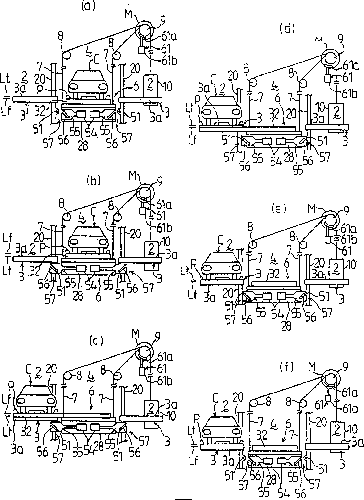
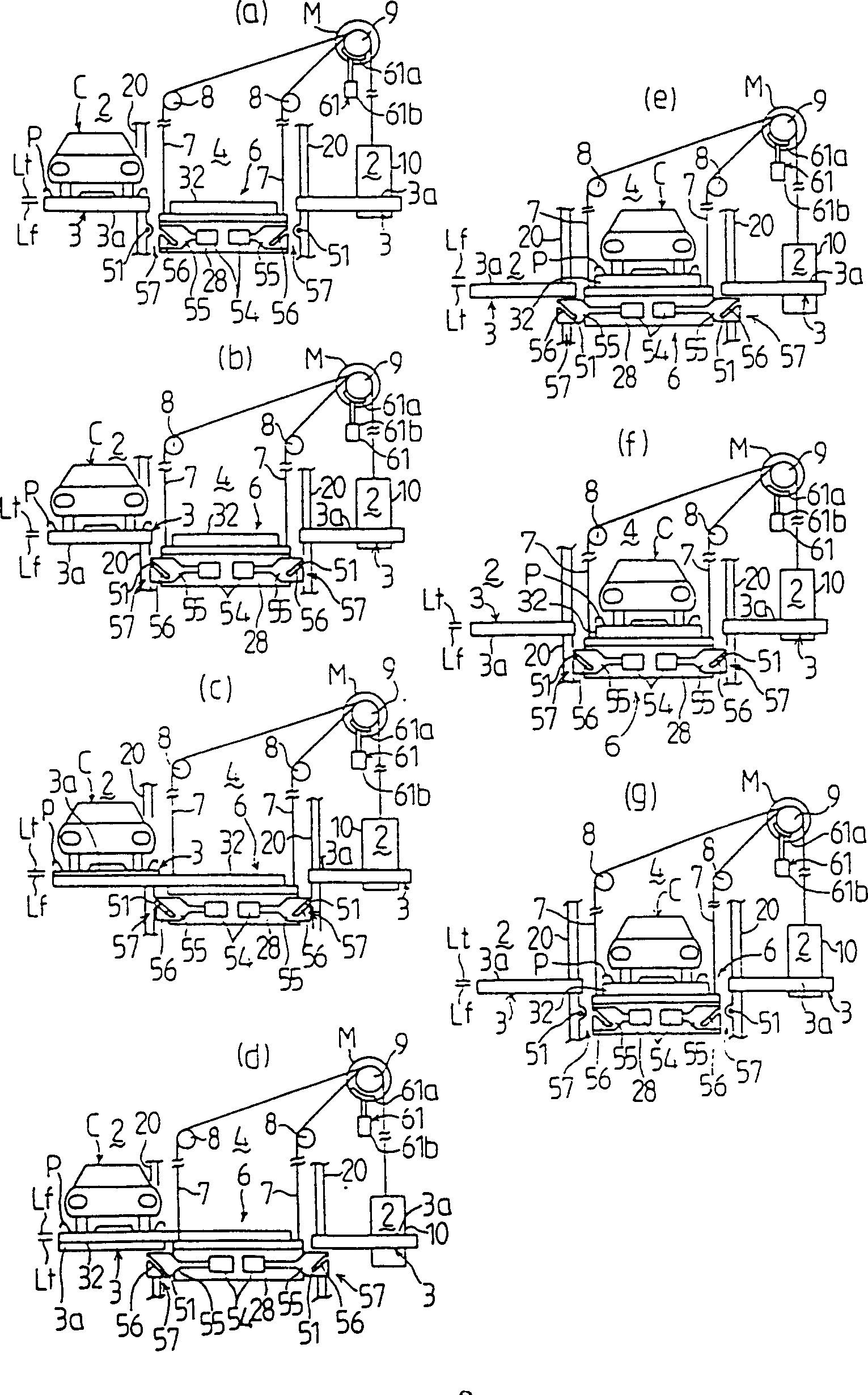
[0046] Figure 15 It shows an elevator-type three-dimensional parking device A using a deposit method from the bottom of an article storage device related to the embodiment of the present invention. In the figure, 1 is a building, 2 is a number of storage spaces arranged on the left and right sides of the parking lot, except for the lower and upper ends of the building 1, and each storage space 2 is equipped with The storage rack 3 of the vehicle C as an article can be stored, and each storage rack 3 can place the pallet portion of the vehicle C as an article.

[0047] The storage places 2 and 2 on the left and right sides are arranged adjacent to the elevator track 4 extending in the vertical direction. In the elevator track 4, the elevator platform 6 as the elevator body constituting the elevator 5 has the four corners of the wire rope 7 ( One end of the linear com...


PUM


Abstract

Disclosed is an equipment for storing articles. One end of a wirerope 7 is connected with a raising platform 6 and the other end is connected with a compensating counterweight through a driving wheel 9 which is driven by a motor M to cause the raising platform 6 to go up and down. The raising platform 6 is provided with a glide clamp plate 32 that transmits vehicles C in and out of a carbarn between the raising platform 6 and a storage shelf 3 in the horizontal direction when the raising platform 6 parks at the side of the storage shelf 3; and the raising platform 6 is also provided with a positioning device 57 which positions accurately a lifter that parks at the side of the storage shelf to be at an upper and a lower positions relatives to the storage shelf according to the up-and-down displacement of the glide clamp plate 32. A control device is arranged for controlling the motor linked with the displacement to keep the wirerope 7 in basically even tension before and after the positioning device 57 displaces upwards and downwards.

Description

Technical field [0001] The invention relates to an article storage device for transferring articles between a lifting body and a storage shelf. Background technique [0002] Generally, in an item storage facility such as an elevator-type three-dimensional parking facility, in order to store items such as inbound vehicles and other items on the storage shelves, or to remove items such as outbound vehicles from the storage shelves, it is necessary to use the elevator platform The goods such as vehicles entering and exiting the warehouse are transported between the elevator body and the storage rack provided adjacent to the elevator corridor of the elevator body. Then, the lifting body is connected to one end of a linear member such as a wire rope, and the other end of the linear member is connected to a counterweight through a driving sheave, and the winding or unwinding of the linear member is operated to make the lifting body follow The hoistway is raised and lowered, and the dri...

Claims


Application Information

Patent Timeline
IPC IPC(8): E04H6/18B65G1/127E04H6/22
Inventor 小井田修一荻野直人前野贤儿
Owner SHIN MEIWA IND CO LTD
Why Eureka
Try Eureka