
Wet desulfurization absorption tower and self-cleaning flue gas dust removal system thereof

A dust removal system and self-cleaning technology, applied in gas treatment, separation methods, chemical instruments and methods, etc., can solve the problems of high dust removal efficiency, large floor area, small dust particle size, etc., to reduce operating costs and maintenance costs Low and low running resistance

Inactive Publication Date: 2017-02-08
YONKER ENVIRONMENTAL PROTECTION
View PDF5 Cites 2 Cited by
  • Summary
  • Abstract
  • Description
  • Claims
  • Application Information

AI Technical Summary

Problems solved by technology

[0006] Dry dust removal + absorption tower + wet electrostatic precipitator process line, the wet dust collector is usually arranged after the desulfurization absorption tower, which can effectively remove the smoke and dust in the flue gas, and has high dust removal efficiency, but it occupies a large area, high investment cost, and high operating cost
Wet electrostatic precipitator equipment is huge, especially for renovation projects, there is not enough space to install wet electrostatic precipitator, and there are many electrical equipment for wet electrostatic precipitator, high operating cost and high maintenance cost
[0007] Dry dedusting + ordinary absorption tower coordinated process line, in order to meet the requirement of "near zero" emission, this process line has the problem of unstable operation, mainly because the absorption tower of this method has no special dust removal equipment, and mainly relies on nozzle mist in the spray area The dust is captured by the liquid droplets and the flue gas droplets are removed by the mist eliminator to remove the dust. However, after the dry dust removal, the dust particle size entering the absorption tower is small, and the spray area of ​​the absorption tower is suitable for fine particle size dust. The capture efficiency is limited, and at the same time, the mist eliminator cannot remove the droplets with a particle size of less than 15um. Therefore, when the inlet dust fluctuates, it is difficult for the outlet dust to reach 3 requirements

Method used


Image

  • Wet desulfurization absorption tower and self-cleaning flue gas dust removal system thereof
  • Wet desulfurization absorption tower and self-cleaning flue gas dust removal system thereof
  • Wet desulfurization absorption tower and self-cleaning flue gas dust removal system thereof

Examples


Embodiment Construction

[0045] The present invention is described below in conjunction with the accompanying drawings, and the examples given are only used to explain the present invention, and are not intended to limit the scope of the present invention.

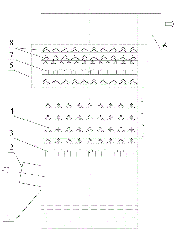
[0046] A wet desulfurization absorption tower, such as figure 1 As shown, the self-cleaning flue gas dust removal system 5 is arranged inside the absorption tower 1. The lower part of the absorption tower 1 is provided with a flue gas inlet 2, and the upper part is provided with a flue gas outlet 6. The flue gas inlet in the absorption tower 1 is Between 2 and the flue gas outlet 6, a through-flow sieve plate 3, a spray area 4, and a self-cleaning flue gas dust removal system 5 are arranged in sequence from bottom to top. The self-cleaning flue gas dedusting system 5 is arranged between the uppermost spray area and the flue gas outlet 6 . The flue gas enters the through-flow sieve plate 3 from the flue gas inlet of the absorption tower, and then ...


PUM

PropertyMeasurementUnit
particle diameteraaaaaaaaaa

Abstract

The invention discloses a self-cleaning flue gas dust removal system used for flue gas purification. The self-cleaning flue gas dust removal system comprises a self-cleaning area and a drop catcher, wherein the self-cleaning area is used for performing replacement dilution on gypsum droplets carried by flue gas and catching fine dust; the drop catcher is at least composed of a primary drop catcher and a second drop catcher and is used for removing drops in the flue gas; the self-cleaning area is arranged between a spraying area and the primary drop catcher and / or between the primary drop catcher and the second drop catcher; and the spraying area, the primary drop catcher and the second drop catcher are used for being arranged in the absorption tower from bottom to top. The dust removal efficiency is met, the arrangement is compact, the occupied land is reduced, the investment is saved, the operation and maintenance are convenient, and the energy consumption of the system is reduced.

Description

technical field [0001] The invention relates to a wet desulfurization absorption tower and its self-cleaning flue gas dust removal system, in particular to an absorption tower equipment capable of efficiently removing solid particles in flue gas. Background technique [0002] In September 2014, the National Development and Reform Commission, the Ministry of Environmental Protection, and the National Energy Administration jointly issued the "Coal Power Energy Conservation and Emission Reduction Upgrading and Transformation Action Plan (2014-2020)" requiring that the emission limits of flue gas pollutants from coal-fired power plants in key areas reach Requirements for gas turbine units, sulfur dioxide emission shall not exceed 35mg / Nm 3 , The concentration of solid particles does not exceed 10mg / Nm 3 , to meet the "ultra-clean emission" requirements. Economically developed areas have proposed that the concentration of solid particles should not exceed 5mg / Nm 3 "Near-Zero E...

Claims


Application Information

Patent Timeline
Patent Type & Authority Applications(China)
IPC IPC(8): B01D50/00B01D53/80B01D53/50B01D47/02
CPCB01D50/00B01D47/028B01D53/502B01D53/504B01D53/80B01D2258/0283
Inventor 龚蔚成邓乾红杨景香姚超良
Owner YONKER ENVIRONMENTAL PROTECTION
Learn More