Supercharge Your Innovation With Domain-Expert AI Agents!

Hyperbolic-type cooling tower for thermal plant

A hyperbolic, cooling tower technology, applied in the cooling field of thermal power plants, can solve the problems such as the inability of the water blocker to collect water, the insufficient spray area, and the ineffective use of the cooling area.

Pending Publication Date: 2020-01-17
河北大唐国际张家口热电有限责任公司
View PDF0 Cites 0 Cited by
  • Summary
  • Abstract
  • Description
  • Claims
  • Application Information

AI Technical Summary

Problems solved by technology

There is a sump at the bottom of the tower, and the cooling device, water distributor, water retainer and beam are arranged in the tower from bottom to top. The beam is arranged in a net shape inside the cooling tower. and the sprinklers arranged on the individual water distribution pipes, the individual water distribution pipes are arranged in a net shape inside the cooling tower and fixed under the beams, since the water retainers are arranged on the water distributors, the heat plant hyperbolic The distance between the heat sink of the type cooling tower and the height of the splash point of the nozzle is 800-1000mm, and the distance between the heat sink and the water retainer is about 1200mm, so that the heat exchange of water in the area between the heat sink and the water retainer The space is too small, so that the water retainer cannot achieve the best water collection effect, part of the water will pass through the gap of the water retainer under the action of the nozzle, and be thrown to the top of the water retainer, affecting the cooling effect
[0003] In addition, the water distribution pipe inside the hyperbolic cooling tower of the thermal power plant is fixed on the side of the crossbeam facing the water collection basin. The single water distribution pipe in the area around the inner wall of the curved cooling tower cannot be fixed on the beam, so the end of the water distribution pipe facing the inner wall of the cooling tower is suspended too long, which is easy to bend, deform or even break
Since there is no water distribution pipe in the area close to the inner wall of the cooling tower, the heat dissipation device in the area around the inner wall of the cooling tower cannot be sprayed, resulting in insufficient spraying area, and the cooling area near the outermost inner wall of the cooling tower cannot be effectively used, reducing cooling efficiency

Method used


Image

  • Hyperbolic-type cooling tower for thermal plant
  • Hyperbolic-type cooling tower for thermal plant
  • Hyperbolic-type cooling tower for thermal plant

Examples


Embodiment 1

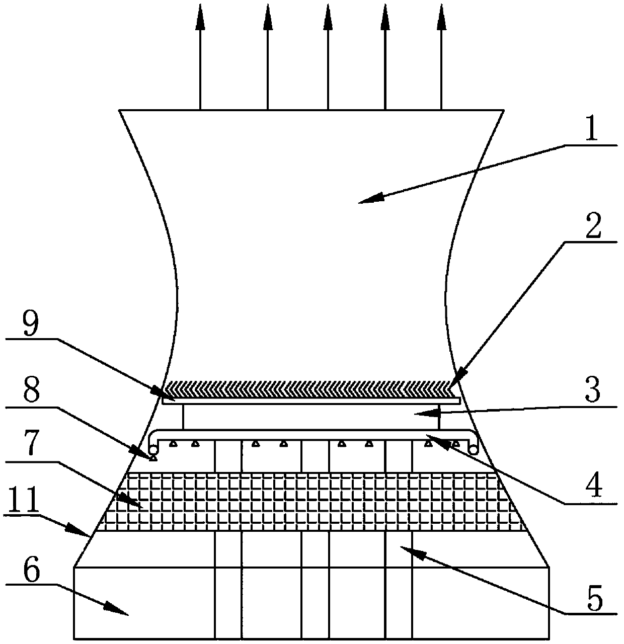
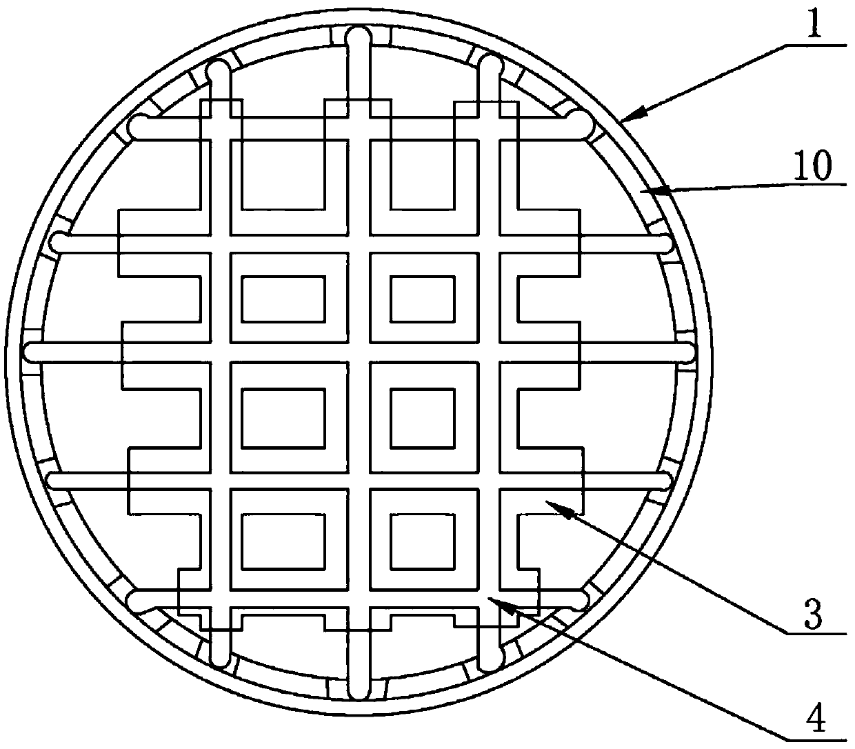
[0032] Such as figure 2 As shown, the supporting beam described in this embodiment includes a horizontal beam 3 arranged along the horizontal direction and a vertical beam 5 supporting the horizontal beam 3 and perpendicular to the horizontal beam 3. There are a plurality of vertical beams 5, and one end of each vertical beam 5 is perpendicular to the set The other end of the water basin 6 passes through the cooling device 7 and is connected to the crossbeam 3, and the crossbeam 3 is supported above the cooling device 7; figure 2 As shown, the water distribution pipes include a plurality of straight individual water distribution pipes 4 connected to each other, and the plurality of individual water distribution pipes 4 are arranged in a network structure inside the tower body and fixed on one side of the beam 6 facing the water collection basin. side, and one end of the single water distribution pipe 4 extends toward the inner wall of the tower, the single water distribution...

Embodiment 2

[0038] The difference between this embodiment and the above-mentioned first embodiment is that the water distribution pipe around the tower is set separately from the single water distribution pipe arranged in a mesh shape inside the cooling tower, and the single water distribution pipe extends to the side where the beam faces the tower wall. The edge position on the side avoids the problems of easy bending, deformation and breakage caused by the excessively long suspension of the single water distribution pipe. The inner wall of the cooling tower is also provided with a rotating device capable of controlling the water distribution pipe around the tower to rotate along the cooling tower, and the water distribution pipe around the tower is separately arranged from the single water distribution pipe. The water distribution pipe around the tower includes three or less circles The arc-shaped pipeline, the arc-shaped pipeline is fixedly connected by a two-way pipe or a flange to for...


PUM


Abstract

The invention discloses a hyperbolic-type cooling tower for a thermal plant. The hyperbolic-type cooling tower comprises an internally hollow cylindrical tower body and a water collection basin at thebottom of the tower body, and a cooling device, a water distributor, a supporting beam and a water defector are arranged in the tower body from bottom to top, wherein the water distributor comprisesa water distributing pipe and water sprayers on the water distributing pipe; the supporting beam comprises transverse beam bodies arranged in the horizontal direction and vertical beam bodies which are perpendicular to the transverse beam bodies and are used for supporting the transverse beam bodies, and the transverse beam bodies are arranged in the tower body in a network structure; the water distributing pipe comprises a plurality of single water distributing pipe bodies which are mutually communicated, the single water distributing pipe bodies are arranged in the tower body in a network structure, the water distributing pipe further comprises a tower-periphery water distributing pipe body which is communicated with the single water distributing pipe bodies, and the tower-periphery water distributing pipe body is circumferentially arranged around the inner wall of the tower body in one circle. Through the arrangement, the space around the inner wall of the tower body is reasonably utilized, and the cooling efficiency is improved.

Description

technical field [0001] The invention belongs to the cooling field of thermal power plants, and in particular relates to a hyperbolic cooling tower for thermal power plants. Background technique [0002] In the prior art, the hyperbolic cooling towers used in thermal power plants are large thin-shell buildings with a hyperbolic shape and built in power plants in areas where water sources are not very sufficient. There is a sump at the bottom of the tower, and the cooling device, water distributor, water retainer and beam are arranged in the tower from bottom to top. The beam is arranged in a net shape inside the cooling tower. and the sprinklers arranged on the individual water distribution pipes, the individual water distribution pipes are arranged in a net shape inside the cooling tower and fixed under the beams, since the water retainers are arranged on the water distributors, the heat plant hyperbolic The distance between the heat sink of the type cooling tower and the h...

Claims


Application Information

Patent Timeline
IPC IPC(8): F28C1/00F28F25/02
CPCF28C1/00F28F25/02
Inventor 赵博冬施利钢贺善举韩举杨凯轩白银帅
Owner 河北大唐国际张家口热电有限责任公司
Features
  • R&D
  • Intellectual Property
  • Life Sciences
  • Materials
  • Tech Scout
  • Unparalleled Data Quality
  • Higher Quality Content
  • 60% Fewer Hallucinations
Learn More