
A deflection measurement system and method based on stereo vision

A technology of stereo vision and deflection measurement, applied in the direction of measuring devices, elastic testing, machine/structural parts testing, etc., can solve the problems of limited detection range, inability to measure in real time, time-consuming and labor-intensive, etc., to improve the accuracy of deflection measurement and benefit Camera calibration, the effect of improving image quality

Active Publication Date: 2021-06-08
武汉中岩科技股份有限公司 +1
View PDF6 Cites 0 Cited by
  • Summary
  • Abstract
  • Description
  • Claims
  • Application Information

AI Technical Summary

Problems solved by technology

[0003] Traditional deflection measurement often uses contact displacement sensors, dial indicators, etc. This method is low in cost and simple in structure, but it is time-consuming and laborious, and cannot be installed under conditions such as crossing rivers and canyons, and cannot be measured in real time.
Optical surveying and mapping instruments such as total stations and theodolites can provide high measurement accuracy, but their detection range is limited, and they can only achieve point-by-point measurement, and cannot achieve large-scale detection of the entire field, resulting in low work efficiency
In recent years, the image measurement method has become a hot spot in the research of large-scale facility deflection non-contact measurement technology, but most of them use monocular vision image measurement method, which needs to use the object of known size in the scene as a reference object to realize the size measurement of the target object , it is not applicable to occasions where the reference object cannot be placed, and there are certain limitations in practical applications; in addition, only using a single camera will compress the pictures collected in the three-dimensional space to a two-dimensional plane, when the target surface of the camera is not parallel to the measured surface , its measurement accuracy will also be greatly affected by

Method used


Image

  • A deflection measurement system and method based on stereo vision
  • A deflection measurement system and method based on stereo vision
  • A deflection measurement system and method based on stereo vision

Examples


Embodiment Construction

[0044] The technical solutions of the present invention will be clearly and completely described below in conjunction with the accompanying drawings in the present invention. Obviously, the described embodiments are only a part of the embodiments of the present invention, not all of them. Based on the embodiments of the present invention, all other embodiments obtained by persons of ordinary skill in the art without making creative efforts belong to the protection scope of the present invention.

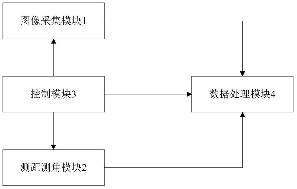
[0045] Such as figure 1 As shown, the present invention provides a deflection measurement system based on stereo vision, including an image acquisition module 1, a distance measurement and angle measurement module 2, a control module 3, and a data processing module 4; wherein, the image acquisition module 1 and the distance measurement and angle measurement module 2 are all connected to the control module 3, the image acquisition module 1, the distance measurement and angle measureme...


PUM


Abstract

The invention discloses a deflection measurement system based on stereo vision, which includes an image acquisition module, a distance measurement and angle measurement module, a control module, and a data processing module. The control module controls the image acquisition module and the distance measurement and angle measurement module to respectively collect data and image acquisition The distance measurement module and the distance measurement module respectively transmit the collected data to the data processing module in real time. The data processing module uses the parallax principle to reconstruct the three-dimensional geometric information of the measured target. The deflection value of each measured point is obtained by changing the spatial coordinates. The invention also discloses a deflection measurement method based on stereo vision. The present invention adopts the mode of double measurement stations, the two measurement stations are independent and have the same structural configuration, which can be used for both close-range measurement and long-distance large field of view measurement. At the same time, the image enhancement algorithm is used to remove the influence of uneven illumination and haze, Improve the accuracy of deflection measurement to better meet the actual needs of engineering testing.

Description

technical field [0001] The invention relates to the technical field of detection and monitoring of large facility engineering structures such as bridges, in particular to a deflection measurement system and method based on stereo vision. Background technique [0002] With the development of national infrastructure construction, different types of bridges, tunnels and other large-scale facilities are constantly emerging. As an important indicator for evaluating the safety and service life of large-scale facility structures, deflection measurement has become an important part of the health and safety assessment of large-scale facility structures. Work. [0003] Traditional deflection measurement often uses contact displacement sensors, dial indicators, etc. This method is low in cost and simple in structure, but it is time-consuming and laborious, cannot be installed under conditions such as crossing rivers and canyons, and cannot be measured in real time. Optical surveying a...

Claims


Application Information

Patent Timeline
Patent Type & Authority Patents(China)
IPC IPC(8): G01M5/00G06T5/00G06T7/70G06T7/80G06T17/00
CPCG01M5/0008G01M5/005G06T17/00G06T7/85G06T7/70G06T5/00
Inventor 赵芳刘少平张东升杨永波邹宇杨鑫刘守华付海孙敏
Owner 武汉中岩科技股份有限公司
Learn More