
Automatic chicken leg and chicken wing separation apparatus used for mass slaughter of black-bone chickens

An automatic separation, large-scale technology, applied to poultry processing support devices, poultry transfer/conveying devices, slaughtering and other directions, can solve problems such as low efficiency and hidden installation hazards, improve safety performance, improve collection effects, and reduce damage. rate effect

Pending Publication Date: 2020-01-21
湖南洪江嵩云禽业有限公司
View PDF0 Cites 2 Cited by
  • Summary
  • Abstract
  • Description
  • Claims
  • Application Information

AI Technical Summary

Problems solved by technology

[0002] The chicken leg is also called the wing root, which is the part of the meat under the chicken wing. Because it looks like a chicken leg and is a little small, it is called a small chicken leg. The wing root and the chicken wing are connected together, so the wing root and the chicken wing need to be aligned after slaughter. Chicken wings are cut and separated. The existing method of separating the wing root and chicken wing in the slaughterhouse is manual separation, using a manual knife to cut or holding the chicken wing and wing root by hand, and cutting and separating it with a fast-rotating cutter head. This is not only inefficient, but also has installation hazards

Method used


Image

  • Automatic chicken leg and chicken wing separation apparatus used for mass slaughter of black-bone chickens
  • Automatic chicken leg and chicken wing separation apparatus used for mass slaughter of black-bone chickens
  • Automatic chicken leg and chicken wing separation apparatus used for mass slaughter of black-bone chickens

Examples


Embodiment Construction

[0024] The following will clearly and completely describe the technical solutions in the embodiments of the present invention with reference to the accompanying drawings in the embodiments of the present invention. Obviously, the described embodiments are only some, not all, embodiments of the present invention. Based on the embodiments of the present invention, all other embodiments obtained by persons of ordinary skill in the art without making creative efforts belong to the protection scope of the present invention.

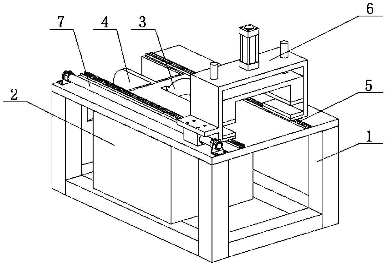
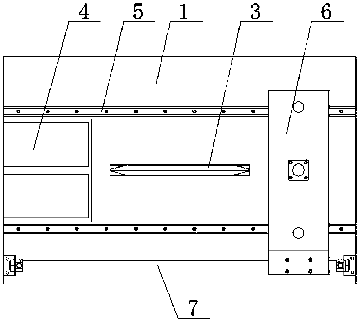
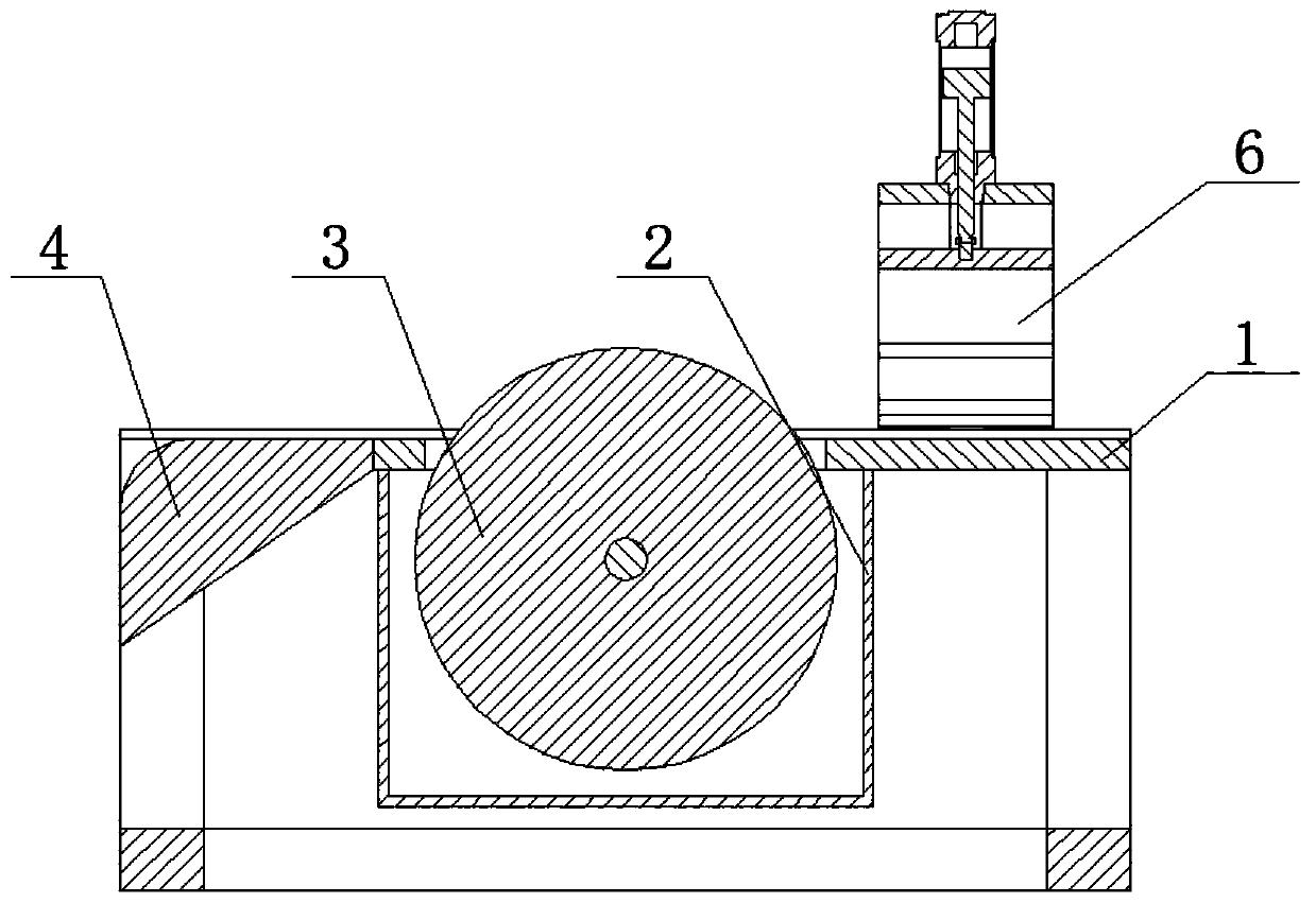
[0025] see Figure 1-6 An automatic separation device for chicken legs and wings for large-scale black-bone chicken slaughter, including an installation platform 1, a protective cover 2 is fixedly installed at the bottom of the installation platform 1, a motor is fixedly installed inside the protective cover 2, and a motor is fixedly sleeved on the output shaft of the motor. The cutter head 3 is fixedly installed with a collecting device 4 on one side of the t...


PUM


Abstract

The invention relates to the technical field of cutting equipment, and discloses an automatic chicken leg and chicken wing separation apparatus used for mass slaughter of black-bone chickens. The automatic chicken leg and chicken wing separation apparatus used for the mass slaughter of the black-bone chickens comprises an installation table; a protective cover is fixedly installed at the bottom ofthe installation table; a motor is fixedly installed inside the protective cover; an output shaft of the motor is fixedly sleeved with a cutter head; a collection device is fixedly installed on one side of a top part of the installation table; and two mutually symmetric guide-rail slider groups are fixedly installed on the top part of the installation table. According to the automatic chicken legand chicken wing separation apparatus used for the mass slaughter of the black-bone chickens, under cooperation of the guide-rail slider groups with a clamping device and a rod-less cylinder, chickenwings and chicken wing tips can be separately clamped by an upper clamping plate and a lower clamping plate; the chicken wings and the chicken wing tips can be prevented from being crushed by a softrubber pad; and the clamping device can be driven to move toward the cutter head by the rod-less cylinder, so that the chicken wings and the chicken wing tips are separated by the cutter head. Therefore, safety performance of the automatic chicken leg and chicken wing separation apparatus used for the mass slaughter of the black-bone chickens is improved.

Description

technical field [0001] The invention relates to the technical field of cutting equipment, in particular to an automatic separation device for chicken legs and chicken wings for mass slaughtering of black-bone chickens. Background technique [0002] The chicken leg is also called the wing root, which is the part of the meat under the chicken wing. Because it looks like a chicken leg and is a little small, it is called a small chicken leg. The wing root and the chicken wing are connected together, so the wing root and the chicken wing need to be aligned after slaughter. Chicken wings are cut and separated. The existing method of separating the wing root and chicken wing in the slaughterhouse is manual separation, using a manual knife to cut or holding the chicken wing and wing root by hand, and cutting and separating it with a fast-rotating cutter head. This is not only inefficient, but also has hidden dangers in installation. Contents of the invention [0003] Aiming at th...

Claims


Application Information

Patent Timeline
Patent Type & Authority Applications(China)
IPC IPC(8): A22C21/00
CPCA22C21/0023A22C21/0053A22C21/0046
Inventor 朱建军
Owner 湖南洪江嵩云禽业有限公司
Learn More