Ultra-high large-span steel reinforced concrete cast-in-place beam formwork reinforcing device and constructing method

A formwork reinforcement and concrete technology, which is applied to formwork/formwork/work frame, on-site preparation of building components, construction, etc. Simple assembly and disassembly, reliable connection effect

Active Publication Date: 2020-01-21
CHINA FIRST METALLURGICAL GROUP
View PDF9 Cites 1 Cited by
  • Summary
  • Abstract
  • Description
  • Claims
  • Application Information

AI Technical Summary

Problems solved by technology

However, steel concrete structural members are high in height, large in span, large in section size, and heavy in weight. During the construction process, a high formwork support system is required, which makes construction difficult, consumes a lot of artificial materials, and is difficult to guarantee safety.
At the same time, the traditional steel concrete structural beam reinforcement construction technology adopts the vertical and horizontal reinforcement of the formwork through the tension screw, which has problems such as large workload, low construction efficiency, and the need to seal the hole of the tension screw left after the formwork is removed.

Method used


Image

  • Ultra-high large-span steel reinforced concrete cast-in-place beam formwork reinforcing device and constructing method
  • Ultra-high large-span steel reinforced concrete cast-in-place beam formwork reinforcing device and constructing method
  • Ultra-high large-span steel reinforced concrete cast-in-place beam formwork reinforcing device and constructing method

Examples


Embodiment Construction

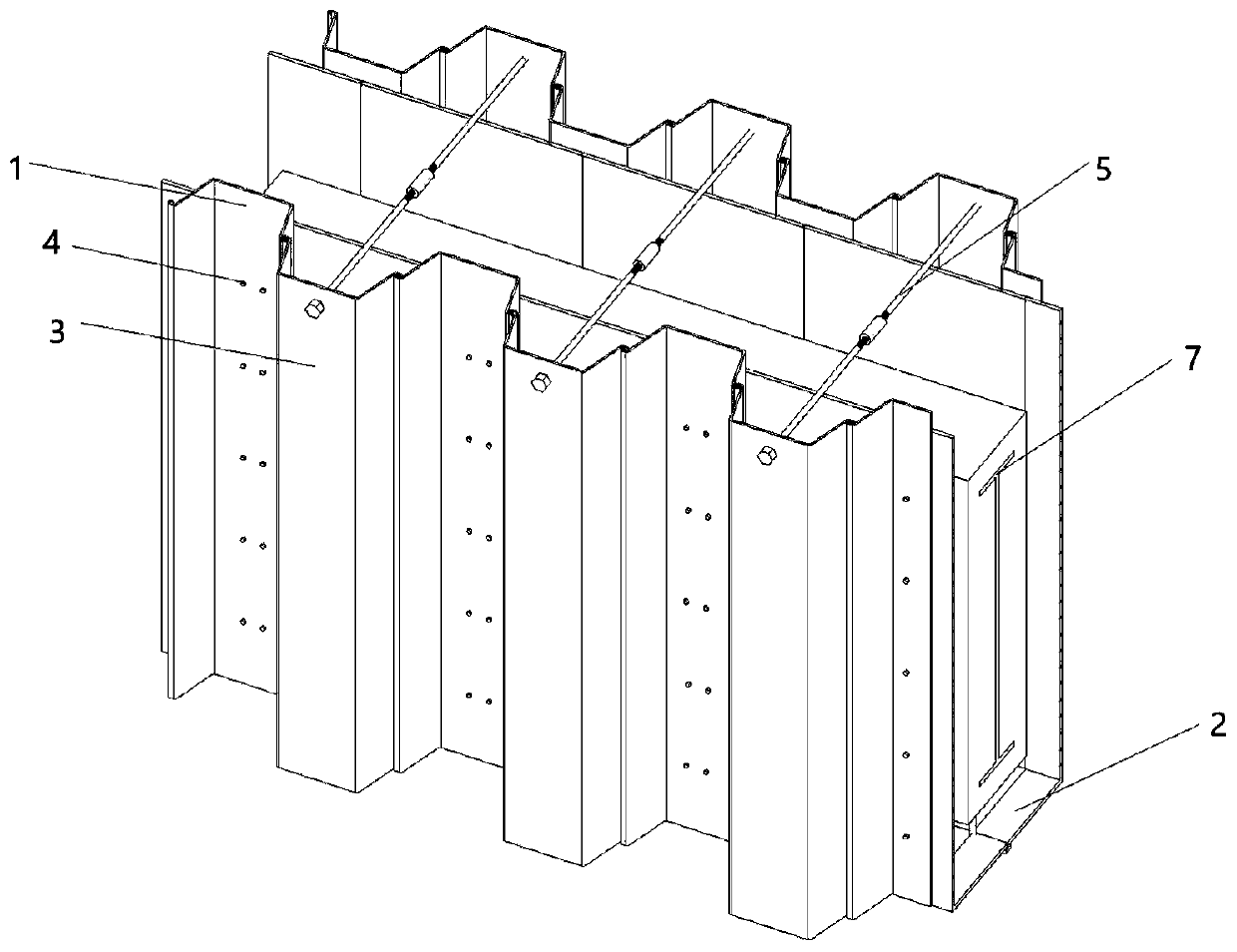
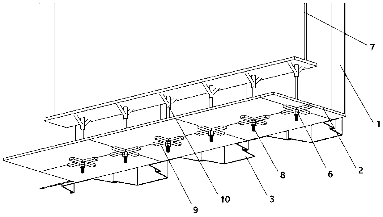
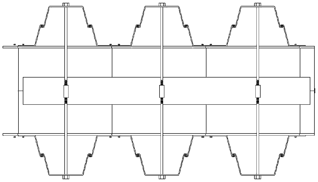
[0031] Such as Figures 1 to 5 As shown, a super-high and large-span steel concrete cast-in-place beam formwork reinforcement device is composed of several reinforcement units. steel beams.

[0032] The beam side formwork and the beam bottom formwork are an integrated L-shaped structure, and the two L-shaped structures are docked to form a U-shaped structure as a whole. The outside of the beam side formwork is fixed by using high-strength bolts and the side back of the Larsen steel plate. The corresponding positions on the beam side formwork and the Larsen steel back flute are preset with through holes, and the tops of the Larsen steel back flute on both sides of the U-shaped structure are connected by round steel tie rods. The round steel tie rod includes a mechanical sleeve and two threaded rods connected with the threaded sleeve. The two threaded rods are located at both ends of the mechanical sleeve, and the two ends are provided with fasteners. The round steel tie rod T...


PUM


Abstract

An ultra-high large-span steel reinforced concrete cast-in-place beam formwork reinforcing device is composed of a plurality of reinforcing units. Each reinforcing unit comprises beam side formworks,beam bottom formworks, Larson steel plate side back edges, a round steel tying rod and a steel reinforced beam, wherein each beam side formwork and the corresponding beam bottom formwork are welded toform an integrated L-shaped structure, the two L-shaped structure are in butt joint to form a U-shaped structure, the outer portions of the beam side formworks are fixed to the Larson steel plate side back edges through high-strength bolts, the tops of the Larson steel plate side back edges on the two sides of the U-shaped structure are connected through the round steel tying rod, the steel reinforced beam is placed in the U-shaped structure, a reserved hole is formed in the joint of the two beam bottom formworks at the bottom of the U-shaped structure, a Y-shaped mechanical sleeve is weldedto the bottom of the steel reinforced beam, a cross-shaped fastener is arranged on the lower side of the reserved hole of the beam bottom formworks, and the mechanical sleeve is connected with the cross-shaped fastener through reverse hoisting bolts. The invention further discloses a constructing method of the ultra-high large-span steel reinforced concrete cast-in-place beam formwork reinforcingdevice.

Description

technical field [0001] The invention relates to the technical field of formwork reinforcement, in particular to a formwork reinforcement device and a construction method for super-high and large-span steel concrete cast-in-place beams. Background technique [0002] The steel concrete structure has the advantages of high bearing capacity, high rigidity, good earthquake resistance and fire resistance, and has been widely used in public buildings with high space and long span in recent years. However, steel concrete structural members are high in height, large in span, large in section size, and heavy in weight. A high formwork support system is required during the construction process. The construction is difficult, the consumption of artificial materials is large, and safety is difficult to guarantee. At the same time, the traditional steel concrete structure beam reinforcement construction technology adopts the vertical and horizontal reinforcement of the formwork through th...

Claims


Application Information

Patent Timeline
Patent Type & Authority Applications(China)
IPC IPC(8): E04G13/04
CPCE04G13/04
Inventor 罗玉龙王东方雅琪王林
Owner CHINA FIRST METALLURGICAL GROUP
Why Eureka
Try Eureka