Leakage detection method for gas supply system of natural gas engine

A leak detection and air supply system technology, which is applied in engine components, engine control, combustion engines, etc., can solve the problems of not ensuring the safety of the air supply system, having a large impact, and not being enough to form an alarm signal.

Inactive Publication Date: 2020-01-21
WEICHAI XIGANG NEW ENERGY POWER
View PDF9 Cites 2 Cited by
  • Summary
  • Abstract
  • Description
  • Claims
  • Application Information

AI Technical Summary

Problems solved by technology

This detection method is greatly affected by the engine operating environment. If the air flow is good when the engine is running, the leaked gas will diffuse quickly, causing the signal detected by the gas sensor to weaken and not enough to form an alarm signal, so the gas supply system cannot be detected in time. The leakage phenomenon
[0003] In addition, there are also two solenoid valves specially used for leak detection installed in series in the gas supply system, which cooperate with the gas pressure sensor and the electronic control unit ECU to complete the leak detection task. off state, so this detection method can only be used when the engine is not started
Specifically: after the electric control unit ECU is powered on, it controls the two solenoid valves to shut off, detects the pressure value of the gas supply pipeline, and judges whether there is leakage in the gas supply pipeline according to the gas pressure drop speed. It can be seen that this detection method can only guarantee The safety of the air supply system before the engine starts cannot be detected during engine operation, and the safety of the air supply system during engine operation cannot be ensured. Therefore, it is necessary to further improve the above-mentioned various leak detection methods

Method used


Image

  • Leakage detection method for gas supply system of natural gas engine

Examples


Embodiment Construction

[0023] Below in conjunction with accompanying drawing and embodiment, further elaborate the present invention. In the following detailed description, certain exemplary embodiments of the invention are described by way of illustration only. Needless to say, those skilled in the art would realize that the described embodiments can be modified in various different ways, all without departing from the spirit and scope of the present invention. Accordingly, the drawings and description are illustrative in nature and not intended to limit the scope of the claims.

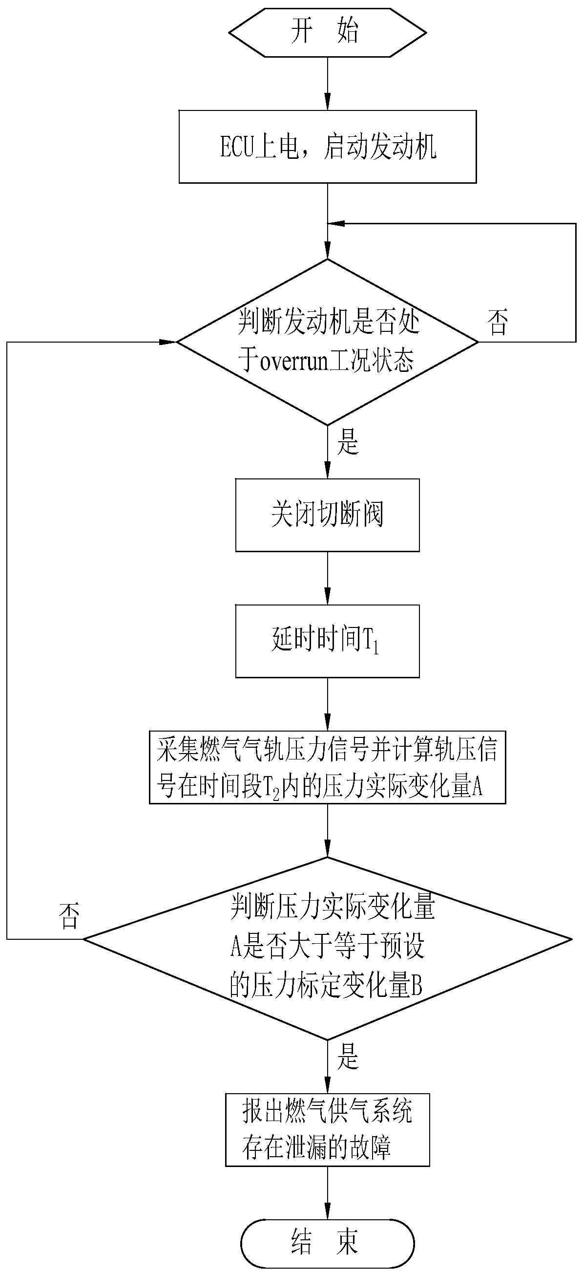
[0024] Such as figure 1 As shown, a leak detection method of a gas supply system for a natural gas engine is completed under the cooperation of the cut-off valve, the injection valve of the gas supply system of the engine, and the electronic control unit ECU on the engine, including the following steps,

[0025] Step 1, the electric control unit ECU is powered on, and the engine is started.

[0026] The electronic cont...


PUM


Abstract

The invention discloses a leakage detection method for a gas supply system of a natural gas engine. The leakage detection method is completed under the cooperation of a stop valve and an injection valve of the gas supply system of the engine and an Electronic Control Unit (ECU) on the engine; when the engine or a whole vehicle runs in an overrun state, the injection valve is in a closed state, atthe moment, the stop valve in the gas supply system is closed through the ECU, a closed channel is formed between the stop valve and the injection valve, and the pressure in the channel is the gas rail pressure. If no gas leakage phenomenon exists, the gas rail pressure should be at a relatively stable value, the change of the gas rail pressure of the engine or the whole vehicle in the running state can be detected through the ECU and compared with the stable value of the gas rail pressure in a normal no-leakage state, and therefore whether leakage exists in the gas supply system or not can bejudged. According to the method, detection, judgment and alarming are automatically completed, detection can be conducted multiple times when the running state is met in the driving cycle of the engine or the whole vehicle, and the running safety of the engine is greatly improved.

Description

technical field [0001] The invention relates to the technical field of engine air supply system monitoring, in particular to a leak detection method for a natural gas engine air supply system. Background technique [0002] The gas supply system of a natural gas engine is mainly composed of gas tanks, gas shut-off valves, voltage regulators, gas supply pipelines, gas rails, injection valves and other components. Failure of any one of these components will cause natural gas to leak, resulting in waste of gas and Air pollution, more importantly, can cause safety hazards in engine operation. At present, there are various technical means for detecting gas leakage during engine operation, such as installing a gas sensor on the engine, using the gas sensor to detect relevant signals in the gas, and processing them through the engine's electronic control unit ECU, and internal preset According to the comparison result, it is determined whether there is a gas leakage phenomenon. Whe...

Claims


Application Information

Patent Timeline
IPC IPC(8): F02D41/22F02M21/02
CPCF02D41/22F02M21/0215F02D2041/225F02D2041/228F02D2200/0602Y02T10/40Y02T10/30
Inventor 孙万超曹石
Owner WEICHAI XIGANG NEW ENERGY POWER
Why Eureka
Try Eureka