Fractionating tower feed distributing structure and fractionating tower

A fractionation tower and feed technology, applied in fractionation, hydrocarbon distillation, distillation separation, etc., can solve the problems of affecting the performance of the distributor fractionation tower, not providing liquid gasification space, reducing the centrifugal gas-liquid separation effect, etc. Liquid separation and distribution effect, significant distribution effect, sufficient gas-liquid separation effect

Active Publication Date: 2020-01-24
SINOPEC ENG +1
View PDF9 Cites 0 Cited by
  • Summary
  • Abstract
  • Description
  • Claims
  • Application Information

AI Technical Summary

Problems solved by technology

The distributor has the function of centrifugal gas-liquid separation, but in order to improve the effect of gas-liquid distribution, deflectors are installed, which seriously reduces the effect of centrifugal gas-liquid separation, and basically does not provide a gasification space for liquid, and lacks a support for rising Distribution facilities for gas and descending liquid, distributed only by the space in the feed section inside the tower
On the other hand, due to the lack of effective support for the descending liquid, the situation that the liquid entrains the gas quickly leaves the feed section under the action of gravity often occurs, which affects the overall performance of the distributor and even the entire fractionation tower.

Method used


Image

  • Fractionating tower feed distributing structure and fractionating tower
  • Fractionating tower feed distributing structure and fractionating tower
  • Fractionating tower feed distributing structure and fractionating tower

Examples


Embodiment 1

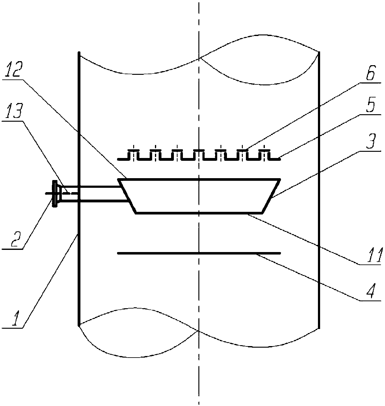
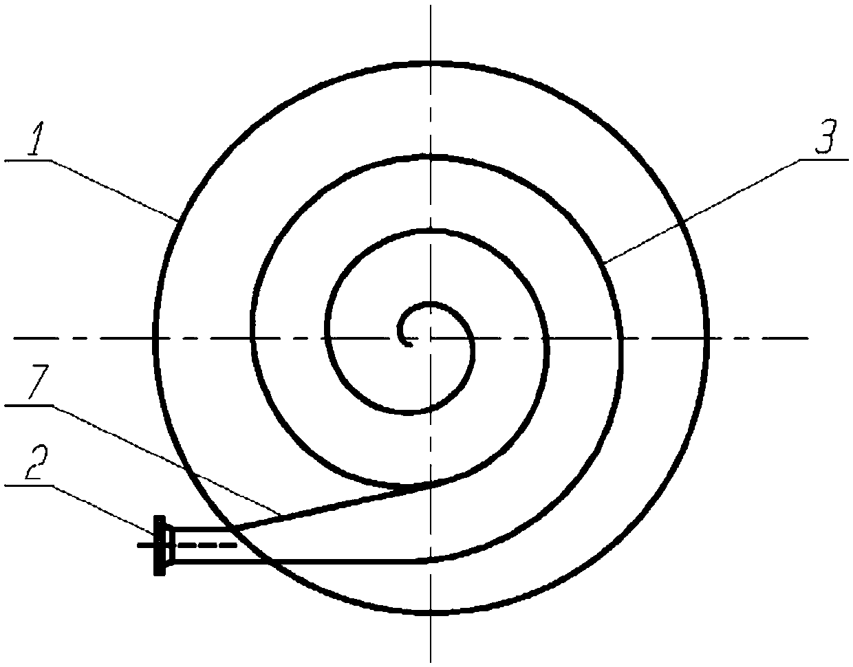
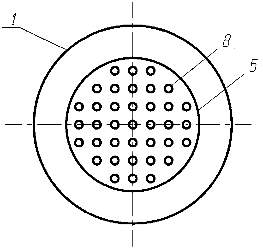
[0033] This embodiment relates to a fractionation tower, such as figure 1 and figure 2 As shown, the fractionation tower comprises: a fractionation tower shell 1, a fractionation tower feed port 2 and a fractionation tower feed distribution structure, and the fractionation tower feed distribution structure includes: a swirl plate 3 arranged inside the fractionation tower, so The swirl plate 3 communicates with the feed port 2 of the fractionation tower through the expander pipe 7; the gas distribution plate 5 arranged directly above the swirl plate 3; the liquid regasification distribution plate 4 arranged directly below the swirl plate 3.

[0034] Such as Figure 4 As shown, one end of the expanding tube 7 is a contracting end 9, and the other end is an expanding end 10. The section of the contracting end 9 is circular and is equal to the feed port 2 of the fractionation column. The section of the expanding end 10 is It is elliptical, tangent to both sides of the inlet of ...

Embodiment 2

[0041] The difference from Embodiment 1 is that the air lift cylinders 8 are arranged in a triangle on the gas distribution plate 5, such as Figure 3b As shown, the cone angle of the cone is 73°, such as Figure 5b As shown, the applicable gas-liquid ratio of the swirl plate in this embodiment is smaller than that in Embodiment 1.

[0042] Adopting the feed distribution structure of the above-mentioned fractionation tower, the gas-liquid separation effect is guaranteed, and the gas and liquid are evenly distributed on the cross-section of the tower, which provides a strong guarantee for the product separation of the fractionation tower.


PUM


Abstract

The invention belongs to the field of equipment of the petrochemical industry, and relates to a fractionating tower feed distributing structure and a fractionating tower. The fractionating tower feeddistributing structure comprises a swirl plate, a gas distributing plate and a liquid regasifying distributing plate, wherein the swirl plate is arranged in the fractionating tower, and a swirl plateinlet is used for communicating with a fractionating tower feeding opening; the gas distributing plate is arranged over the swirl plate; and the liquid regasifying distributing plate is arranged underthe swirl plate. The fractionating tower feed distributing structure is simple in design, gas-liquid separation is fully conducted, a distributing effect of rising gas and falling liquid is significant, gas-liquid separating and distributing effects of a feeding segment can be guaranteed, liquid entrainment in the gas and gas entrainment in the liquid are retarded and even eliminated, and meanwhile, a liquid gasifying space is provided, so that the mass transfer performance of the fractionating tower is guaranteed.

Description

technical field [0001] The invention belongs to the field of petrochemical equipment, and more specifically relates to a fractionation tower feed distribution structure and the fractionation tower. Background technique [0002] In the mass transfer and fractionation equipment used in industrial production such as oil refining and petrochemical industry, packed towers and plate towers belong to the main two categories. Regardless of the type of equipment, the separation of the gas-liquid two-phase in the feed section and the uniform distribution on the column section are the key issues that need to be solved in the internal structure of the column. The gas-liquid separation and distribution in the feed section belongs to the initial separation distribution, which has an important impact on the separation efficiency, product quality and yield of the entire distillation column. The unsatisfactory gas-liquid separation and distribution in the feed section is difficult to make u...

Claims


Application Information

Patent Timeline
Patent Type & Authority Applications(China)
IPC IPC(8): B01D3/16B01D3/32C10G7/00
CPCB01D3/16B01D3/324C10G7/00
Inventor 王亚彪张成袁毅夫
Owner SINOPEC ENG
Why Eureka
Try Eureka