
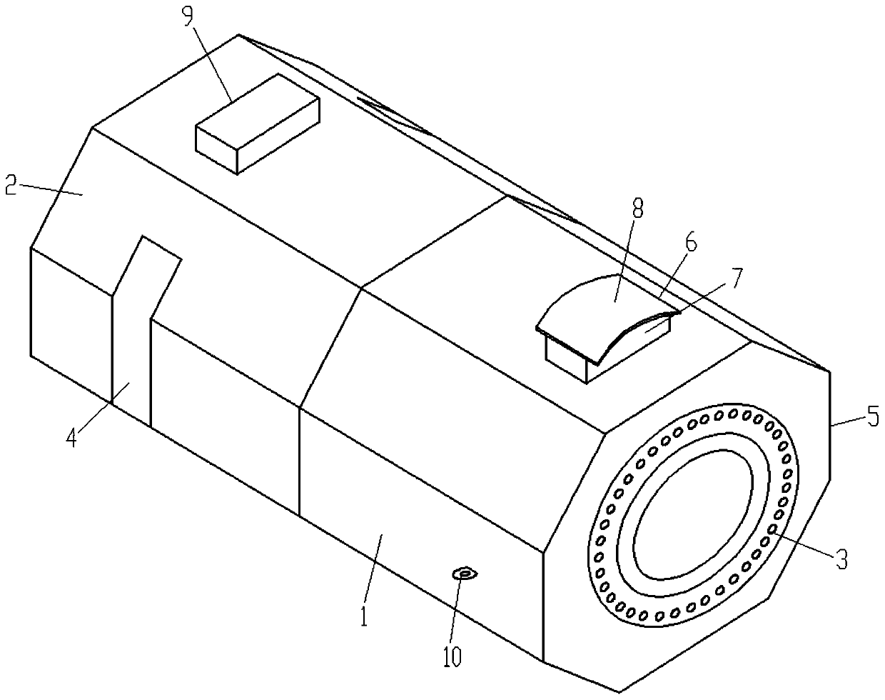
Shield tunneling machine shell structure favorable for escape

A technology of shield machine and shell, which is applied in mining equipment, earth-moving drilling, tunnels, etc., can solve the problems of reduced work efficiency, difficulty in getting out of trouble for the shield machine, and the shield machine cannot work normally, and achieves high anti-torsion performance. , the effect of improving stability

Pending Publication Date: 2020-01-24
刘永顺
View PDF0 Cites 0 Cited by
  • Summary
  • Abstract
  • Description
  • Claims
  • Application Information

AI Technical Summary

Problems solved by technology

The shell structure of the small shield machine currently in use is generally cylindrical. Due to the round and smooth surface of the shield machine with this cylindrical shell structure, it is easy to make the gap between the shell surface and the hole wall during the drilling process. It is filled with slag, and with the drilling movement of the shield machine, the slag between the shell and the wall will become more and more dense due to the rounded effect of the cylindrical shell structure without edges and corners, and finally the shield machine will It is firmly trapped, and the dense filling of the muck makes it very difficult for the shield machine to be released manually, resulting in the shield machine not working normally and greatly reducing the work efficiency

Method used


Image

  • Shield tunneling machine shell structure favorable for escape

Examples


Embodiment Construction

[0014] The technical solutions in the embodiments of the present invention will be clearly and completely described below in conjunction with the accompanying drawings in the embodiments of the present invention. Obviously, the described embodiments are only a part of the embodiments of the present invention, rather than all the embodiments. Based on the embodiments of the present invention, all other embodiments obtained by those of ordinary skill in the art without creative work shall fall within the protection scope of the present invention.

[0015] In the present invention, the terms "including", "including" or any other variations thereof are intended to cover non-exclusive inclusion, so that a process, method, article or device including a series of elements not only includes those elements, but also includes no Other elements clearly listed, or also include elements inherent to this process, method, article or equipment. Without more restrictions. An element defined by t...


PUM

PropertyMeasurementUnit
Thicknessaaaaaaaaaa

Abstract

The invention provides a shield tunneling machine shell structure favorable for escape. The shield tunneling machine shell structure comprises a front shield shell and a rear shield shell, and the rear end of the front shield shell and the front end of the rear shield shell are axially and slidably sleeved and connected. The cross-section outline structures of the front shield shell and the rear shield shell are both of polygonal structures, edges and corners are formed on the outer surface of a shell, large and uneven gaps are formed between the shield tunneling machine shell and a cave wall,and therefore the shield tunneling machine is easy to escape. Through the effect of the edges and the corners of the polygons of the front shield shell and the rear shield shell, in the rotary drilling process of a shield tunneling machine rotary disc, a shield tunneling machine body has great resistance to ring torsion, and the stability of the shield tunneling machine is improved.

Description

Technical field [0001] The invention belongs to the technical field of shield machines, and in particular relates to a shield machine shell structure that is beneficial to escape difficulties. Background technique [0002] At present, the construction of hard rock tunnels with small diameter tunnels can be constructed with small shield machines, which not only solves the problems of traditional manual drilling and blasting methods such as harsh construction environment, slow construction speed, high construction cost, high risk, and high construction accident rate. Moreover, the automatic mechanization of hard rock tunnel excavation is realized, and work efficiency is improved. The shell structure of the small shield machine currently in use is generally a cylindrical structure. Because the surface of the cylindrical shell structure of the shield machine is round and smooth, it is easy to make the surface of the shell and the wall of the hole during the drilling process. Filled ...

Claims


Application Information

Patent Timeline
IPC IPC(8): E21D9/06
CPCE21D9/06
Inventor 刘永顺王立志
Owner 刘永顺
Learn More