
Multi-channel ball valve structure, electric ball valve and application of electric ball valve

An electric ball valve, multi-channel technology, applied in the direction of multi-way valve, valve shell structure, valve details, etc., can solve the problems that affect the development prospects of deep diving equipment, unsatisfactory sealing effect, inconvenient operation, etc., to achieve light weight, valve Compact structure and improved sealing effect

Pending Publication Date: 2020-01-24
江西中船阀门成套装备有限公司
View PDF0 Cites 4 Cited by
  • Summary
  • Abstract
  • Description
  • Claims
  • Application Information

AI Technical Summary

Problems solved by technology

[0003] Ball valves are mainly used to cut off or connect the medium in the pipeline, and can also be used for the regulation and control of the fluid, while the pipeline needs to control the confluence, diversion, and switching of the flow direction of the medium, requiring multiple valves to work together, such as deep diving equipment In the technical field, four manual shut-off valves are generally required to control the confluence, diversion, and flow direction switching of the medium on the drainage system pipeline of deep diving equipment. These four manual shut-off valves not only occupy a large space, but are inconvenient to operate, and the sealing effect is not ideal. , the flow resistance coefficient is large, which seriously affects the development prospects of deep diving equipment, so it is urgent to design a multi-channel integrated valve to replace the original four manual stop valve structure

Method used


Image

  • Multi-channel ball valve structure, electric ball valve and application of electric ball valve
  • Multi-channel ball valve structure, electric ball valve and application of electric ball valve
  • Multi-channel ball valve structure, electric ball valve and application of electric ball valve

Examples


Embodiment 1

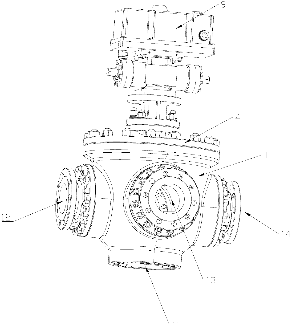
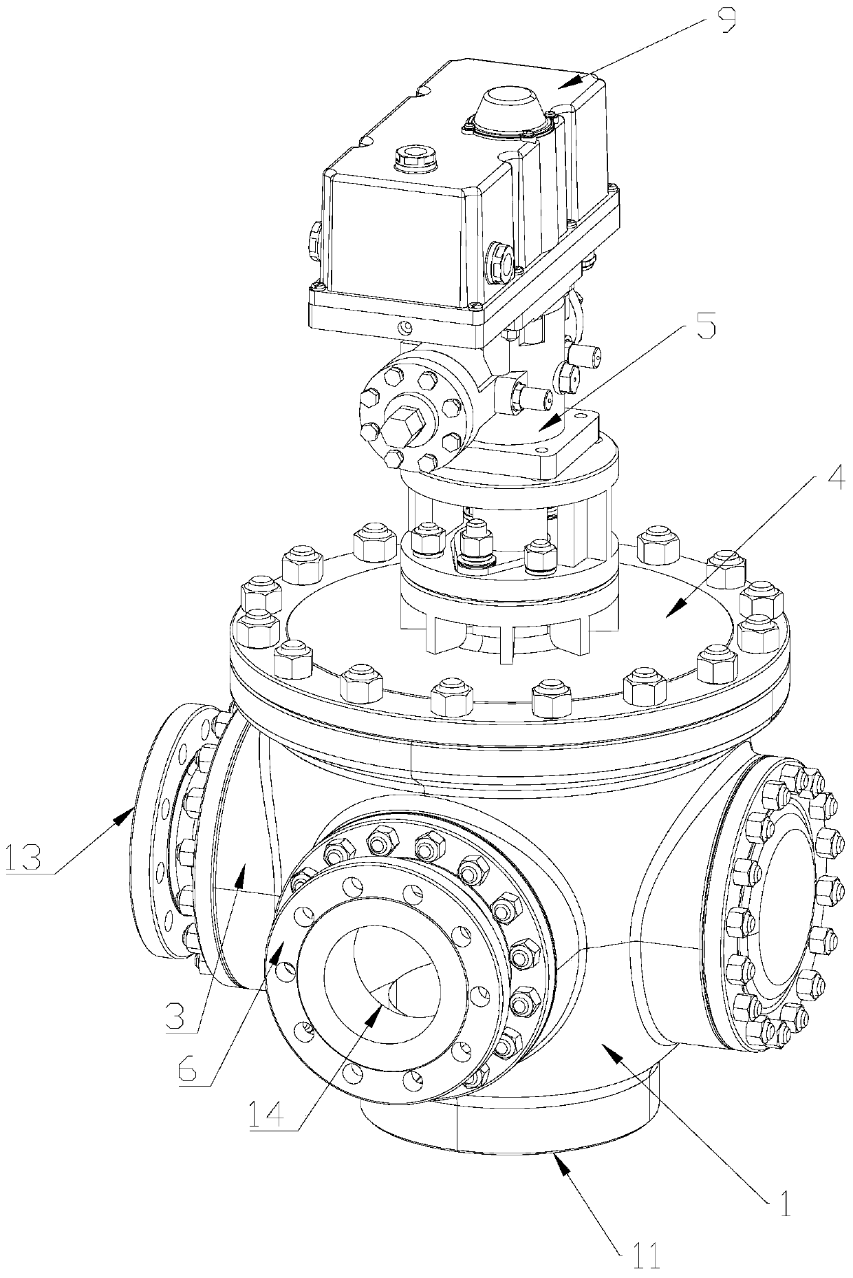
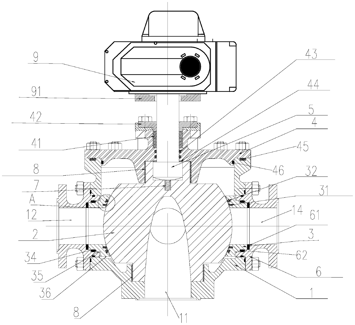
[0037] Such as Figure 1~5 As shown, the multi-channel ball valve structure of the present invention includes a valve body 1, a valve ball 2 arranged in the valve body 1, and a valve cover 4 for closing the valve body 1, and the upper end of the valve ball 2 is connected with The valve stem 5 runs through the valve cover 4; the valve ball 2 is driven to rotate by rotating the valve stem 5, so as to realize the opening and closing of the valve.

[0038] The valve body 1 is provided with inlet 11, inlet 2 12, outlet 13 and outlet 2 14 connected with other pipelines; the inlet 11 is arranged on the bottom wall of the valve body 1 for connecting the feed pipe The inlet and outlet two 12, the outlet one 13 and the outlet two 14 are arranged on the side wall of the valve body 1 for connecting the discharge pipe or the shunt pipe.

[0039] The side wall of the valve ball 2 is provided with a second channel port, a third channel port, a fourth channel port, a fifth channel port, and ...

Embodiment 2

[0044] This embodiment is improved on the basis of Embodiment 1. Specifically, the ball valve also includes a valve seat 3 arranged in the valve body 1, and the valve seat 3 is located at both ends of the valve ball 2, so A sealing seat 31 and a triangular ring sealing seat 32 are provided between the valve seat 3 and the valve ball 2 to realize the sealing between the valve seat 1 and the valve ball 2 .

[0045] Specifically, one end of the sealing seat 31 is arranged on the valve seat 3, and the end surface of the other end is arc-shaped, and fits in an arc shape with the outer wall of the valve ball 2, so that the other end of the sealing seat 31 is in contact with the valve ball. 2. The outer wall fits against each other to realize the first seal between the valve seat 1 and the valve ball 2. In this embodiment, the sealing seat 31 is made of polytetrafluoroethylene glass fiber material.

[0046] Specifically, the bottom end of the triangular ring sealing seat 32 is arrang...

Embodiment 3

[0049] This embodiment is improved on the basis of the second embodiment. Specifically, the ball valve also includes connecting flanges 6 arranged at the inlet 11, the second inlet 12, the first outlet 13 and the second outlet 14. external piping.

[0050] The end surface of the valve seat 3 is stepped, and the connection between the outermost end surface of the valve seat 3 and the connection flange 6 is provided with a metal graphite winding gasket 61 for sealing. The valve seat 3 includes a first stepped surface 34 , a second stepped surface 35 , and a third stepped surface 36 , and a second sealing ring 62 is provided at the connection between the first stepped surface 34 and the connecting flange 6 .

[0051] Therefore, the valve seat 3 and the connecting flange 6 of the present invention are double-sealed through the metal graphite wound gasket 61 and the second sealing ring 62 .


PUM


Abstract

The invention discloses a multi-channel ball valve structure and an electric ball valve, and relates to the technical field of valves. The ball valve structure comprises a valve body, a valve ball anda valve cover, wherein a valve rod is connected with the valve ball, the valve body is provided with an inlet, an inlet II, an outlet I and an outlet II which are connected with a pipeline, the valveball is provided with a first channel, a second channel, a third channel, a fourth channel and a fifth channel, the inlet communicates with the first channel, the second channel and the third channelare 45 degrees, and the third channel and the fourth channel are 45 degrees, and the electric ball valve comprises the ball valve structure and an electric actuator. The invention further discloses an application of the electric ball valve. The multi-channel ball valve structure, the electric ball valve and the application of the electric ball valve have the beneficial effects that the size is small, the weight is light, the installation and maintenance are convenient, and four stop valves in the prior art are replaced; and at the same time, at least a double sealing structure is adopted, thesealing form is reliable, and the sealing effect of the ball valve is improved.

Description

technical field [0001] The invention relates to the technical field of valves, in particular to a multi-channel ball valve structure, an electric ball valve and applications thereof. Background technique [0002] At present, ball valves are widely used in petroleum refining, long-distance pipelines, chemical industry, papermaking, pharmaceuticals, water conservancy, electric power, municipal administration, steel and other industries, and occupy a pivotal position in the national economy. [0003] Ball valves are mainly used to cut off or connect the medium in the pipeline, and can also be used for the regulation and control of the fluid, while the pipeline needs to control the confluence, diversion, and switching of the flow direction of the medium, requiring multiple valves to work together, such as deep diving equipment In the technical field, four manual shut-off valves are generally required to control the confluence, diversion, and flow direction switching of the mediu...

Claims


Application Information

Patent Timeline
IPC IPC(8): F16K11/087F16K5/08F16K41/02F16K27/06F16K27/08
CPCF16K11/0873F16K5/0605F16K5/0647F16K5/0663F16K5/0694F16K27/067F16K27/08
Inventor 刘号群孙平王超宁张惺华蒋重霞余永强余佳宇
Owner 江西中船阀门成套装备有限公司
Learn More