High-current coupler for storage battery car

A high-current, coupler technology, applied in the direction of electric vehicle charging technology, coupling devices, electric vehicles, etc., can solve the problems of difficult to adapt to high-current battery modules, loose sockets, inconvenient operation, etc., so that it is not easy to loosen and fall off , Reliable plugging, and the effect of improving safety

Pending Publication Date: 2020-01-24
乐清市发达科技有限公司
View PDF1 Cites 0 Cited by
  • Summary
  • Abstract
  • Description
  • Claims
  • Application Information

AI Technical Summary

Problems solved by technology

However, with this connection method, it is necessary to plug and unplug the battery module in the correct direction every time when disassembling and assembling the battery module, which is inconvenient to operate. Frequent plugging and unplugging may easily cause loosening of the plug joint and make it poor contact. In addition, With the improvement of vehicle battery life and performance requirements, the traditional electrical connection method of T-type plug and charging interface is difficult to adapt to high-current batteries or battery modules, which has certain potential safety hazards.

Method used


Image

  • High-current coupler for storage battery car
  • High-current coupler for storage battery car
  • High-current coupler for storage battery car

Examples


Embodiment Construction

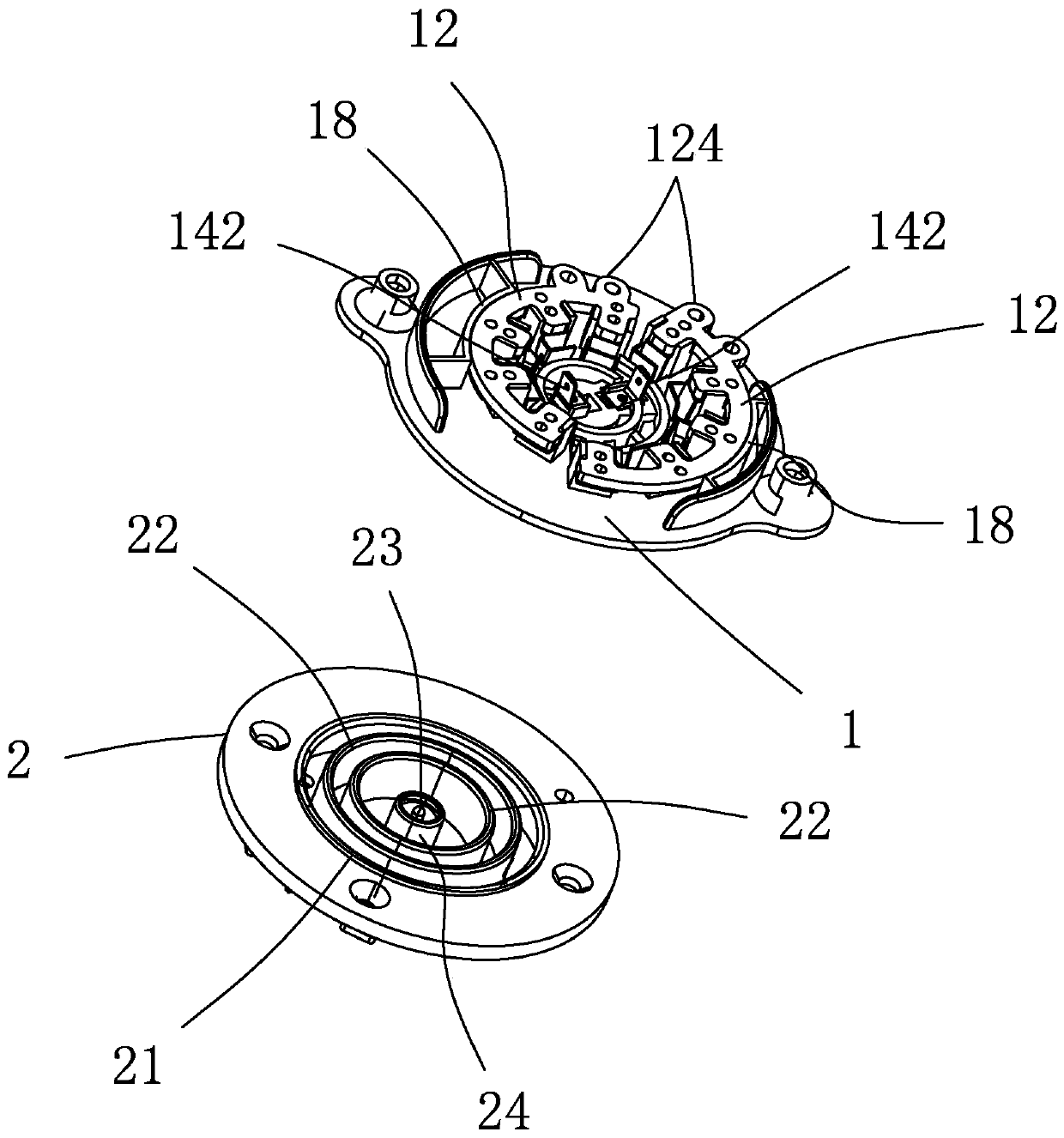
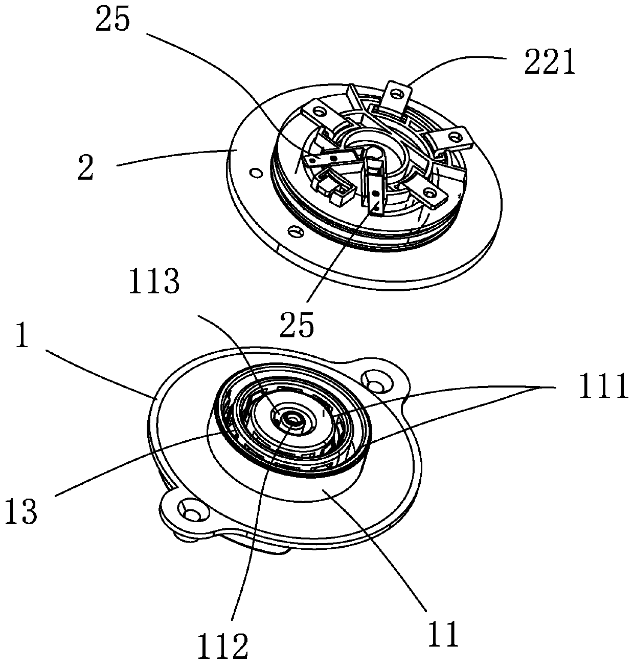
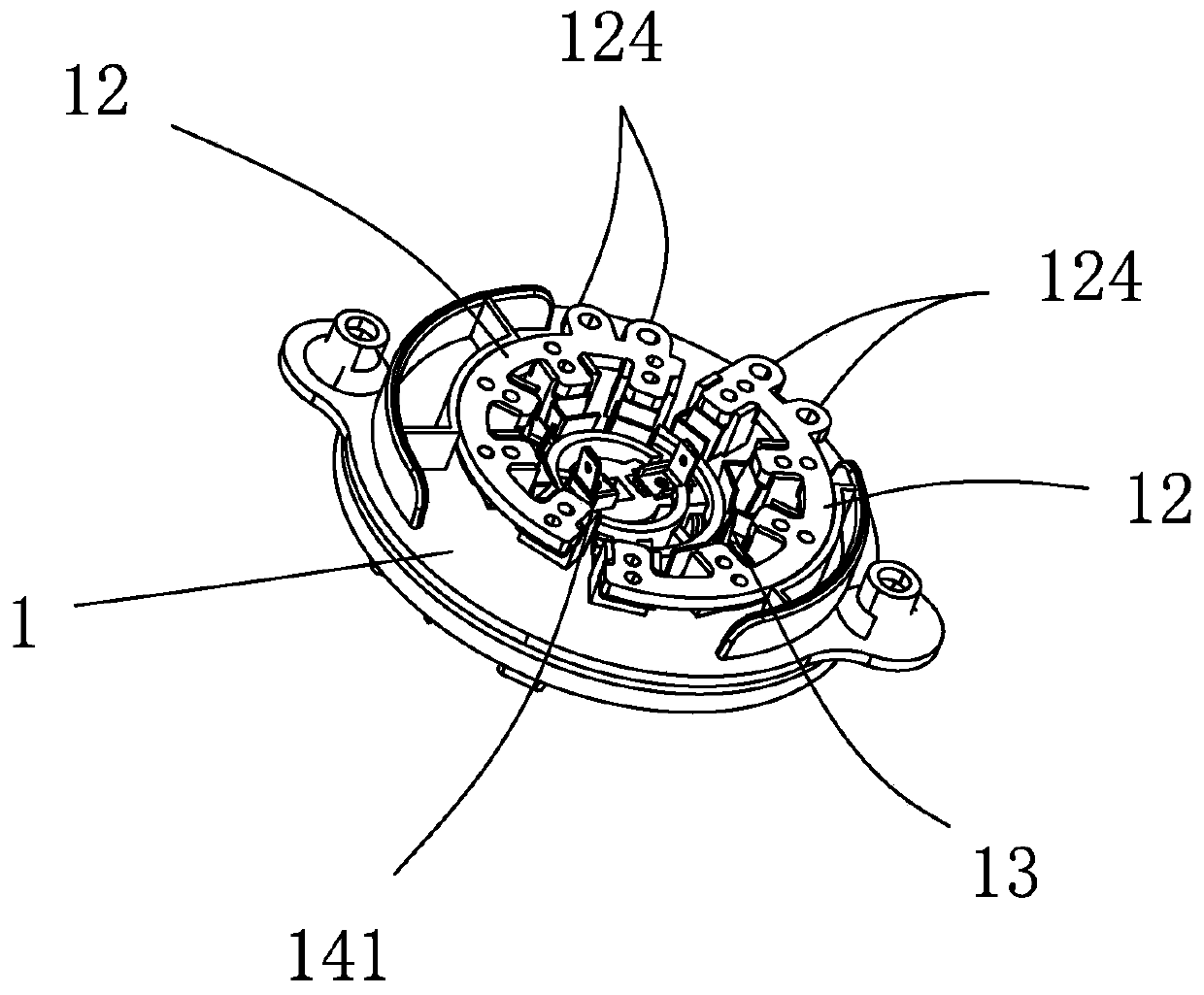
[0040] The embodiment of the large current coupler used in the battery car of the present invention is for example Figure 1-15 As shown: it includes a first coupling piece 1 and a second coupling piece 2 that are mated and plugged in. The first coupling piece 1 is provided with a relatively protruding plug-in part 11 on one end surface of the plug-in part 11. Two first annular slots 111 are concentrically arranged corresponding to the positive and negative poles of the circuit, and the other end surface of the first coupling member 1 is provided with two conductive sheets 12 corresponding to the first annular slots 111. Conductive strips 12 are provided corresponding to two first annular slots 111 respectively, and the two conductive strips 12 are respectively used to connect with the positive and negative poles during current transmission, and each conductive strip 12 is connected with multiple The first electrical contact strips 13 in an annular slot 111, these first electr...


PUM


Abstract

The invention discloses a high-current coupler for a storage battery car. The high-current coupler comprises a first coupling piece and a second coupling piece which are in insertion matching with each other; the end surface of one side of the first coupling piece is provided with an insertion connection part which protrudes relative to the end surface of one side of the first coupling piece; twofirst annular insertion grooves are concentrically formed in the insertion connection part; two conductive sheets corresponding to the first annular insertion grooves are arranged on the end surface of the other side of the first coupling piece; a plurality of first electric contact sheets arranged in the first annular insertion grooves are connected onto the conductive sheets; the first electriccontact sheets arranged in the first annular insertion grooves are arranged at intervals in the circumferential direction of the first annular insertion grooves; a pit which is in insertion matching with the insertion connection part is formed in the end surface of one side of the second coupling piece; and two annular second electric contact sheets are concentrically arranged in the pit. The high-current coupler of the invention has the advantages of structural simplicity, convenience in connection and disconnection and reliable insertion connection, and is more suitable for being applied toa large-current storage battery or a battery module and can improve safety performance.

Description

technical field [0001] The invention relates to a large current coupler used on a battery car. Background technique [0002] Traditional two-wheel, three-wheel or four-wheel battery vehicles usually have a built-in battery or battery module. The power module on the vehicle is connected to the positive and negative poles on the battery or battery module through conductive clips or electrode copper sheets. It can realize the charging or power supply of the battery or battery module. Because of this connection method between the battery and the power module, it is very inconvenient to disassemble and assemble the two. Generally, it is only used when the battery or battery module needs to be repaired and replaced. for disassembly. [0003] Then a kind of charging interface as disclosed in the patent document CN205944572U appeared on the market. It includes an interface body. The T-shaped plug, through the T-shaped plug and the charging interface of the battery module, can real...

Claims


Application Information

Patent Timeline
Patent Type & Authority Applications(China)
IPC IPC(8): H01R24/00H01R13/02H01R13/04H01R13/10H01R13/46B60L53/16
CPCB60L53/16H01R13/02H01R13/04H01R13/10H01R13/46H01R24/00H01R2201/26Y02T10/70Y02T10/7072Y02T90/14
Inventor 季德荣李军
Owner 乐清市发达科技有限公司
Why Eureka
Try Eureka