
Controlled switching control device

A control device, opening and closing technology, applied in the direction of circuit devices, emergency protection circuit devices, emergency protection circuit devices for limiting overcurrent/overvoltage, etc., can solve complex installation and structure, unsatisfactory control effect, increase Intermediary links and other issues to achieve the effect of extending the maintenance cycle and service life, eliminating electromagnetic transient effects, and reducing insulation requirements

Inactive Publication Date: 2020-01-24
JIANGSU ELECTRIC POWER CO +1
View PDF2 Cites 5 Cited by
  • Summary
  • Abstract
  • Description
  • Claims
  • Application Information

AI Technical Summary

Problems solved by technology

The traditional method of suppressing inrush current and overvoltage has the following disadvantages, whether it is installing closing resistors or setting arresters: complex installation and structure, poor reliability, high cost, and strict requirements on the level of insulation structure; complicating the internal structure of the circuit breaker , which increases the intermediate link and reduces the reliability; in some cases, the control effect of a single measure is not ideal, and other measures are still needed to assist and the parameter calculation is complicated; the arrester has a blind area, is large in size, and is easy to age. For example, the continuous operating voltage will Damage to the zinc oxide valve plate, etc.
Its products have the following disadvantages: 1. Generally, only single-phase voltage reference is used, and there is no three-phase voltage reference function
2. Poor adaptability, no self-learning and self-correction capabilities: only for a certain type of switch, or external parameter compensation must be a known condition, and cannot be automatically obtained and corrected in real time
3. Does not have the function of automatic judgment and intelligent switching of compensation mode and adaptive mode

Method used


Image

  • Controlled switching control device
  • Controlled switching control device
  • Controlled switching control device

Examples


Embodiment 1)

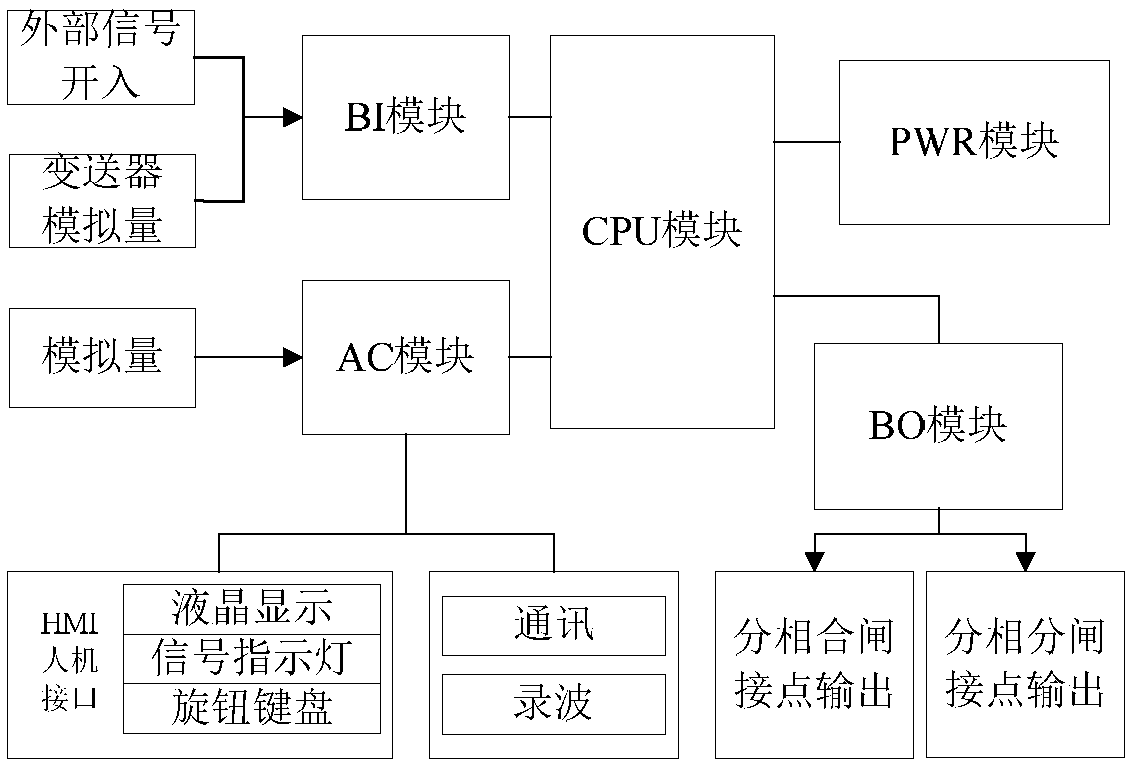
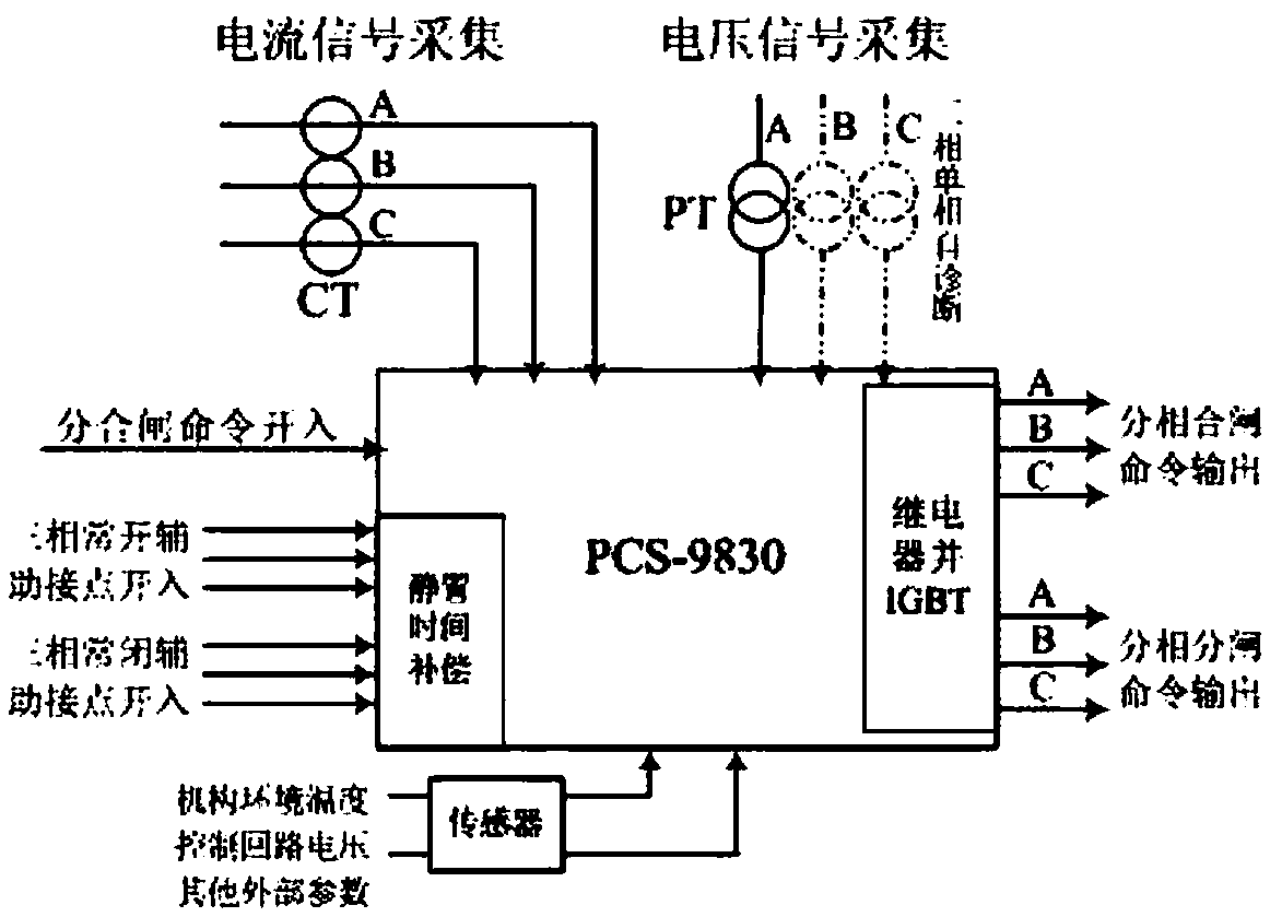
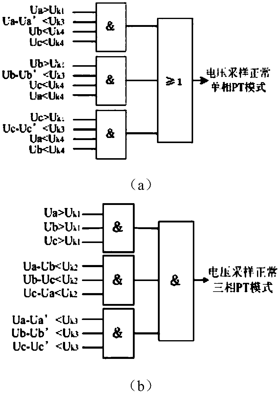
[0014] Such as figure 1 Shown: The power supply module (PWR module) provides DC power to the unit. The analog input module (i.e. AC module) provides 3 channels of voltage and 3 channels of current sampling channels to collect system voltage and current signals in real time, open the phase selection control program when the voltage acquisition is normal, otherwise block this function; use current acquisition to accurately determine Instantaneous electrical switching. In addition to executing the main program of controlled opening and closing and coordinating various boards, the CPU module also has the opening and closing command input of the monitoring control system, and the position contact input can be connected to the normally open auxiliary contact of the three-phase circuit breaker and the normally closed three-phase circuit breaker. The auxiliary contact can use the position signal combined with the relay action delay to determine the opening and closing time. The swit...


PUM


Abstract

The invention provides a controlled switching control device. The device comprises a CPU module, an alternating-current analog quantity input plug-in, a switching quantity transmitter signal input plug-in, a power source module and a switching quantity output plug-in. With the controlled switching control device of the invention adopted, electromagnetic transient effects such as inrush current andovervoltage generated in a switching process can be actively eliminated, the stabilization of system voltage is facilitated, the maintenance periods and service lives of a circuit breaker and power equipment are prolonged.

Description

technical field [0001] The invention relates to a phase selection opening and closing control device of a circuit breaker, which is suitable for the phase selection opening and closing control of electric equipment in an AC station and a DC converter station. Background technique [0002] Under the background of the State Grid Corporation's promotion of UHV AC and DC transmission technology, the problem of overvoltage in UHV power grids has become prominent. The traditional method of suppressing inrush current and overvoltage has the following disadvantages, whether it is installing closing resistors or setting arresters: complex installation and structure, poor reliability, high cost, and strict requirements on the level of insulation structure; complicating the internal structure of the circuit breaker , which increases the intermediate link and reduces the reliability; in some cases, the control effect of a single measure is not ideal, and other measures are still needed ...

Claims


Application Information

Patent Timeline
Patent Type & Authority Applications(China)
IPC IPC(8): H02H9/00
CPCH02H9/00
Inventor 曹良李萧严会君
Owner JIANGSU ELECTRIC POWER CO
Learn More