Hydraulic camshaft adjuster, and method for operating the hydraulic camshaft adjuster

A camshaft adjuster, hydraulic technology, applied in the direction of machine/engine, engine lubrication, engine components, etc., can solve problems such as expensive and troublesome, and achieve the effect of reducing the risk of aggregation

Active Publication Date: 2020-01-24
SCHAEFFLER TECH AG & CO KG
View PDF11 Cites 1 Cited by
  • Summary
  • Abstract
  • Description
  • Claims
  • Application Information

AI Technical Summary

Problems solved by technology

[0005] However, the known solutions have the disadvantage that they are either very cumbersome and therefore relatively expensive, or that under certain (unfavorable) operating conditions it is not possible to ensure that the support chamber for adjusting the camshaft adjuster to the central position is adequately supply oil
The disadvantage is that the pressure medium stored in the reservoir during engine shutdown is limited to a certain fill level due to overflow on the adjusting magnet of the hydraulic camshaft adjuster

Method used


Image

  • Hydraulic camshaft adjuster, and method for operating the hydraulic camshaft adjuster
  • Hydraulic camshaft adjuster, and method for operating the hydraulic camshaft adjuster
  • Hydraulic camshaft adjuster, and method for operating the hydraulic camshaft adjuster

Examples


Embodiment Construction

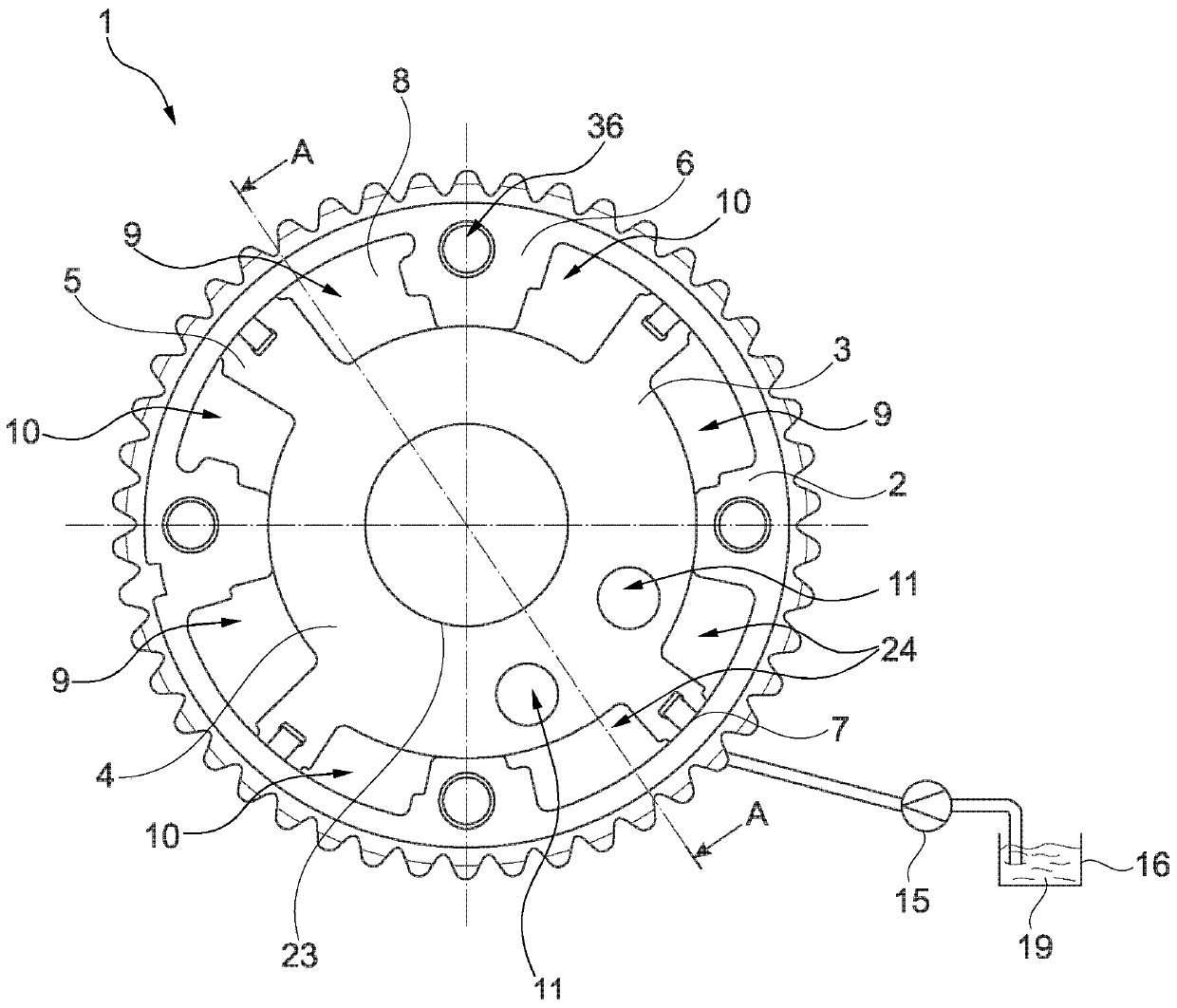
[0028] exist figure 1 An exemplary embodiment of a hydraulic camshaft adjuster 1 according to the invention is shown in FIG. 1 , which is used for adjusting the valve timing of an internal combustion engine. exist figure 1 The hydraulic camshaft adjuster 1 shown schematically in the figure is configured in a known manner as a vane adjuster and comprises a stator 2 that can be driven by the crankshaft of the internal combustion engine, not shown here, and a The camshaft is connected to the rotor 3 in a rotationally fixed manner. The rotor 3 has a rotor hub 4 from which a plurality of blades 5 extend in radial direction. In the illustration shown, a hydraulic camshaft adjuster 1 is shown with a stator 2 and a rotor 3 in section. The stator 2 has webs 6 which divide the annular space between the stator 2 and the rotor 3 into pressure chambers 8 . The pressure chambers 8 are divided by the vanes 5 of the rotor 3 into two groups of working chambers 9 , 10 with different directi...


PUM


Abstract

The invention relates to a hydraulic camshaft adjuster (1) for adjusting the control time of gas exchange valves of an internal combustion engine, comprising a stator (2) which can be synchronously rotated by the crankshaft of the internal combustion engine, and a rotor (3) which is mounted so as to rotate with the stator (2), and which can synchronously rotate with the camshaft, several ribs (6)being provided on the stator (2), the ribs dividing an annular chamber (7) between the stator (2) and the rotor (3) into a plurality of pressure chambers (8), wherein the rotor (3) comprises a rotor hub (4) and a plurality of vanes (5) extending radially outward from the rotor hub (3), the pressure chamber (8) being divided into two groups of working chambers (9, 10) having a different direction of work and being impinged upon by respectively a pressure medium (19) upstream or downstream in a pressure medium circuit, and comprising a central locking mechanism (11) for locking the rotor (3) ina central position, wherein the hydraulic camshaft adjuster (1) is connected at least partially to a front side (20, 21) by a cover (17, 18), wherein a reservoir (14) for storing the pressure medium (19) is formed in one of the covers (17, 18). The cover (17, 18) comprises an overflow opening (23) through which the pressure medium (19) can exit in the axial direction from the hydraulic camshaft adjuster (1), and wherein the reservoir (14) is dimensioned in relation to the overflow opening (23) such that when the hydraulic camshaft adjuster (1) is at a standstill, a pressure medium (25) remainsat the bottom in the reservoir (14), which ensures the pressure medium is supplied to the return valve (28) of the central locking mechanism (11) when the hydraulic camshaft adjuster (1) is running.The invention also relates to a method for operating said type of camshaft adjuster (1).

Description

technical field [0001] The invention relates to a hydraulic camshaft adjuster and a method for operating a hydraulic camshaft adjuster according to the preambles of the independent claims. Background technique [0002] Hydraulic camshaft adjusters are used in internal combustion engines to adapt the load state of the internal combustion engine to increase the efficiency of the internal combustion engine. Numerous hydraulic camshaft adjusters which operate according to the vane principle are known from the prior art. These camshaft adjusters usually have, in their basic construction, a stator which can be driven by the crankshaft of the internal combustion engine and a rotor which is connected in a rotationally fixed manner to the camshaft of the internal combustion engine. An annular space is arranged between the stator and the rotor, and this annular space is divided into a plurality of working chambers by radially inwardly protruding protrusions connected to the stator in...

Claims


Application Information

Patent Timeline
Patent Type & Authority Applications(China)
IPC IPC(8): F01L1/344
CPCF01L1/3442F01L2001/34446F01L2001/34463F01L2001/34469F01L2001/34426F01L2001/34456F01M9/106
Inventor 格哈德·沙伊迪希约亨·蒂伦伊诺·施米特
Owner SCHAEFFLER TECH AG & CO KG
Why Eureka
Try Eureka