
Programmable micro-valve device and control method for micro-flow transportation by using programmable micro-valve device

A micro-valve and micro-fluid technology, which is used in laboratory containers, chemical instruments and methods, laboratory utensils, etc., can solve the problems of leakage between the micro-valve and the micro-channel, and achieves a solution that facilitates organic integration and solves leakage problems. Effect

Pending Publication Date: 2020-01-31
武夷学院
View PDF0 Cites 0 Cited by
  • Summary
  • Abstract
  • Description
  • Claims
  • Application Information

AI Technical Summary

Problems solved by technology

However, the disadvantage of this programmable microvalve is that it needs to ensure that the holes in the cylindrical polylactic acid rod are at exactly the same height as the microchannel holes, so that when the microvalve is in the open state, the microfluid in the microchannel can pass through the cylinder. The hole in the polylactic acid rod reaches the other side of the microchannel. The programmable microvalve disconnects the microchannel. There is a risk of leakage between the microvalve and the microchannel, which needs to be improved

Method used


Image

  • Programmable micro-valve device and control method for micro-flow transportation by using programmable micro-valve device
  • Programmable micro-valve device and control method for micro-flow transportation by using programmable micro-valve device
  • Programmable micro-valve device and control method for micro-flow transportation by using programmable micro-valve device

Examples


Embodiment 1

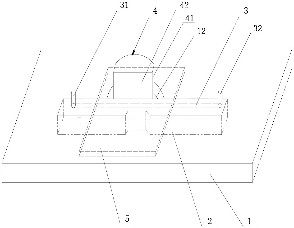
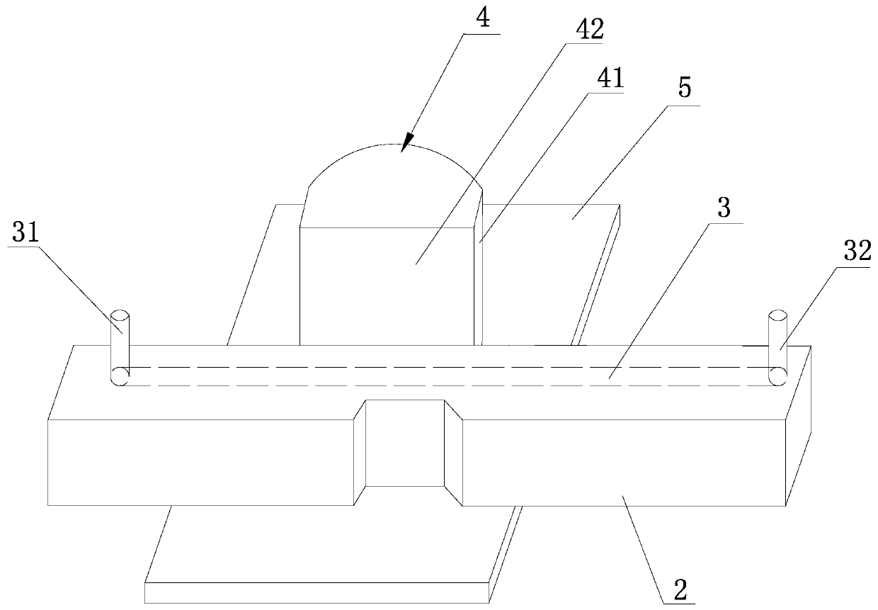
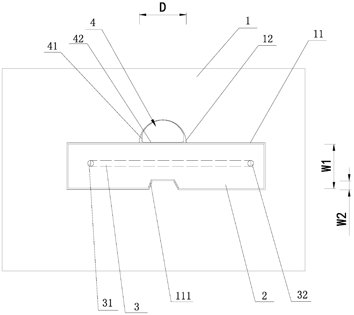
[0022] A programmable microvalve device proposed in this embodiment, as shown in the figure, includes a printed circuit board 1, and the printed circuit board 1 is hollowed out up and down with a concave part 111 on one side in the width direction. A rectangular hole 11 and a shaft hole 12, the shaft hole 12 is close to the other side of the width direction of the rectangular hole 11 and communicates with the rectangular hole 11, the position of the shaft hole 12 is directly opposite to the position of the concave part 111, the rectangular hole 11 is embedded with a PDMS cured body 2 that is compatible with the rectangular hole 11. The PDMS cured body 2 is provided with a microchannel 3 along the length direction, and a rotating rod 4 is vertically placed in the shaft hole 12. The rotating rod 4 is initially When the microchannel 3 is unblocked, the programmable microvalve device is in the open state; the rotating rod 4 is rotated 90 degrees to squeeze the PDMS solidified body ...

Embodiment 2

[0029] This embodiment proposes a control method for microfluidic transport using the programmable microvalve device of Embodiment 1, which includes the following steps:

[0030] The microfluid is injected through the inlet 31 of the microchannel 3, and the microfluid flows towards the outlet 32 ​​of the microchannel 3; if the operator decides to close the programmable microvalve device, the operator rotates the rotating rod 4 clockwise or counterclockwise to make it Rotate 90 degrees, at this time the side plane 41 of the rotating rod 4 is in contact with one side in the width direction of the PDMS cured body 2, the rotating rod 4 squeezes the PDMS cured body 2, and the concave part 111 is facing the semi-cylindrical hole, that is, rotates The side plane 41 of the rod 4 faces the protruding part corresponding to the concave part 111 on the printed circuit board 1. Under the action of the rotating rod 4 and the protruding part on the printed circuit board 1, the deformation of ...


PUM

PropertyMeasurementUnit
Widthaaaaaaaaaa
Apertureaaaaaaaaaa

Abstract

The invention discloses a programmable micro-valve device and a control method for micro-flow transportation by using the programmable micro-valve device. The programmable micro-valve device comprisesa printed circuit board; the printed circuit board is provided with a rectangular hole and a shaft hole in a penetrating and up-down hollowed-out mode, wherein the rectangular hole is provided with aconcave part on one side in the width direction; the shaft hole is next to the other side of the width direction of the rectangular hole and is communicated with the rectangular hole; the shaft holeis opposite to the concave part in position; a PDMS solidified body matched with the rectangular hole is embedded in the rectangular hole, a micro-channel is formed in the PDMS solidified body in thelength direction; a rotating rod is vertically arranged in the shaft hole; the micro-channel is unblocked when the rotating rod is at an initial state, and the micro-channel is at an open state at themoment; after the rotating rod rotates by 90 degrees, the rotating rod extrudes the PDMS solidified body, the micro-channel deforms and is converted into a blocked state, and at the moment, the micro-channel is at a closed state. The advantages are that the risk of leakage of the micro-channel does not exist in movement, and the requirement of micro-fluidic analysis capable of being integrated ina printed circuit board can be met.

Description

technical field [0001] The invention relates to a micro-valve device and control technology for controlling micro-fluid transport in a micro-fluid control chip, in particular to a programmable micro-valve device and a control method for micro-fluid transport using the same. Background technique [0002] The control of microfluidic flow direction is the basis of microfluidic analysis system for microfluidic analysis. Microvalve is the basic unit to realize the control of microfluidic flow direction. Therefore, with the deepening of the research on the mechanism and structure of microvalve, new microvalve mechanism and microvalve structure continue to appear, thus expanding the application range of microfluidic analysis. , making microfluidic analysis widely used in DNA analysis, cell analysis, protein analysis, drug detection, environmental monitoring and food safety and other fields. [0003] According to whether an external power source is required, microvalves can be divi...

Claims


Application Information

Patent Timeline
IPC IPC(8): B01L3/00
CPCB01L3/5027
Inventor 章安良
Owner 武夷学院
Learn More