
Circular shaft clamping tool

A technology for clamping tooling and round shafts, used in workpiece clamping devices, hand-held tools, manufacturing tools, etc., can solve problems such as easily damaged shaft surfaces, and achieve the effects of low manufacturing cost, easy processing and small footprint

Pending Publication Date: 2020-01-31
中船桂江造船有限公司
View PDF0 Cites 0 Cited by
  • Summary
  • Abstract
  • Description
  • Claims
  • Application Information

AI Technical Summary

Problems solved by technology

[0003] The problem to be solved by the present invention is to provide a round shaft clamping tool, which can solve the problem that the shaft surface is easily damaged when clamping each shaft segment for rotation

Method used


Image

  • Circular shaft clamping tool

Examples


Embodiment 1

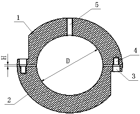
[0017] Such as figure 1 A circular shaft clamping tool shown includes a first clamping block 1 and a second clamping block 2 connected by bolts, the distance between the first clamping block 1 and the second clamping block 2 is H, and the first clamping block The distance H between the block 1 and the second clamping block 2 is 2 mm. On the inside of the first clamping block 1 and the second clamping block 2, arc-shaped clamping surfaces are arranged symmetrically. The two arc-shaped clamping surfaces form a clamping cavity with a circular cross section. The cross-sectional diameter of the clamping cavity is D The size is the required clamping shaft diameter d+0.5mm. A screw mounting hole 5 is provided on the outer side of the first clamping block 1 .

[0018] On both sides of the arc-shaped clamping surface on the first clamping block 1 and the second clamping block 2, there are light holes 3 and threaded holes 4 for mounting bolts respectively, and the light holes 3 of the...

Embodiment 2

[0021] The difference between this embodiment and embodiment 1 is that the distance H between the first clamping block 1 and the second clamping block 2 is 3 mm. All the other features are the same as in Example 1.


PUM


Abstract

The invention discloses a circular shaft clamping tool, and relates to the technical field of ship manufacturing. The circular shaft clamping tool comprises a first clamping block and a second clamping block which are connected through a bolt, wherein the distance between the first clamping block and the second clamping block is H; arc-shaped clamping surfaces are symmetrically arranged on the inner sides of the first clamping block and the second clamping block; the two arc-shaped clamping surfaces form a clamping cavity with a circular cross section; a screw mounting hole is formed in the outer side of the first clamping block; the diameter D of the cross section of the clamping cavity is the required diameter d + 0.5mm of a clamping shaft; and the distance H between the first clamping block and the second clamping block is 2-3mm. Compared with the prior art, the circular shaft clamping tool has the advantages that the first clamping block and the second clamping block are connectedthrough the bolt to clamp a shaft section, a screw mounted on the screw mounting hole of the first clamping block is pulled to rotate the shaft section, and the arc-shaped clamping surfaces of the first clamping block and the second clamping block are matched with the outer circular surface of the shaft section to clamp the shaft section, so that the surface of the shaft is prevented from being damaged.

Description

technical field [0001] The invention relates to the technical field of shipbuilding, in particular to a circular shaft clamping tool for rotating each shaft section when a ship shaft system is centered and installed. Background technique [0002] Ship shafting is the general term for the power transmission components from the output end of the main engine to the propeller. Thrust bearings in the hull are transmitted to the hull so that the ship sails according to the driving instructions. The reliable operation of ship shafting depends not only on the structural design of the shafting, but also on the installation quality of the shafting. The shafting installation directly affects the installation quality of the shafting. During the shafting installation process, each shaft section needs to be clamped separately for rotation, and the cross section of each shaft section is circular. Since there is no special circular shaft clamp It is easy to damage the surface of the shaft...

Claims


Application Information

Patent Timeline
IPC IPC(8): B25B11/02B25B27/00
CPCB25B11/02B25B27/00
Inventor 吕玉权
Owner 中船桂江造船有限公司
Learn More