Crane lifting arm for rapid installation

A technology for installation and crane, which is applied in the direction of transportation and packaging, load hanging components, etc. It can solve the problems that affect the installation progress, consume manpower and time, and the bottom of the iron tower is not easy to align with the installation base, so as to improve the installation efficiency. The effect of improving the degree of cleanliness

Active Publication Date: 2020-01-31
淮北亚荣科技有限公司
View PDF4 Cites 2 Cited by
  • Summary
  • Abstract
  • Description
  • Claims
  • Application Information

AI Technical Summary

Problems solved by technology

In the past, the erection of overhead transmission line iron towers was completed by continuously erecting angle steels one by one. Using this method to erect towers requires a lot of manpower and time. Now there are special cranes for erecting. The iron tower is hoisted and placed. The lifting arm on the crane is a structure similar to a wrench. After clamping the iron tower, it is lifted upwards.
[0003] Because the existing lifting arm is clamped from left to right when clamping, when the moving speed is fast, it is easy to make the iron tower tilted. After hoisting to the installation position, the bottom of the iron tower is not easy to align with the installation base, which increases the difficulty of installation. ,
[0004] During emergency construction, the iron tower is clamped and fixed only by the fixing plate installed on the peripheral board. Although it can play a certain role in fixing, it still cannot avoid the inclination of the iron tower, which greatly affects the installation progress in the emergency construction state. At the same time The dust generated by standing still on the iron tower for a long time and the dust impurities in the air will lead to a bad construction environment, thereby affecting the construction efficiency and the cleanliness of the environment during construction; in view of this, the present invention provides a crane boom for quick installation

Method used


Image

  • Crane lifting arm for rapid installation
  • Crane lifting arm for rapid installation
  • Crane lifting arm for rapid installation

Examples


Embodiment Construction

[0026] In order to make the technical means, creative features, goals and effects achieved by the present invention easy to understand, the present invention will be further described below in conjunction with specific embodiments.

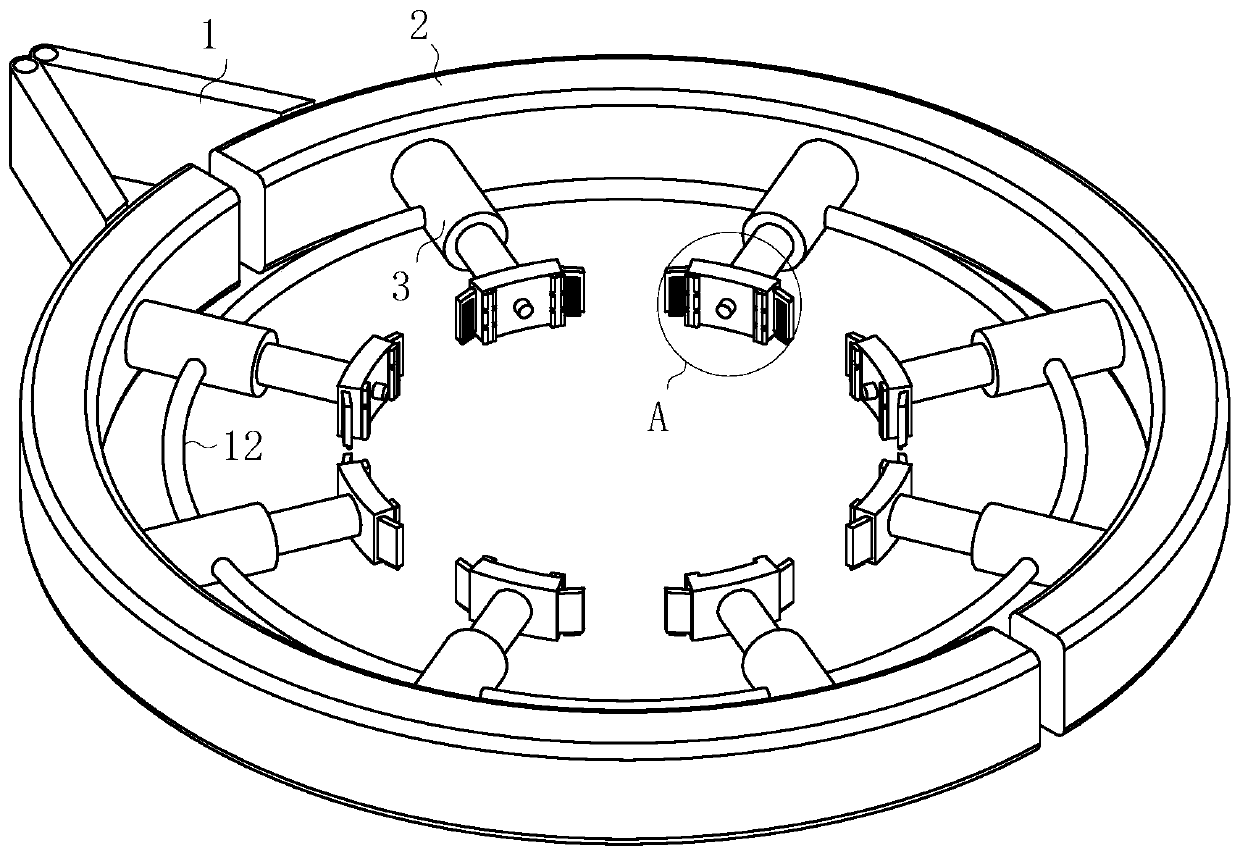
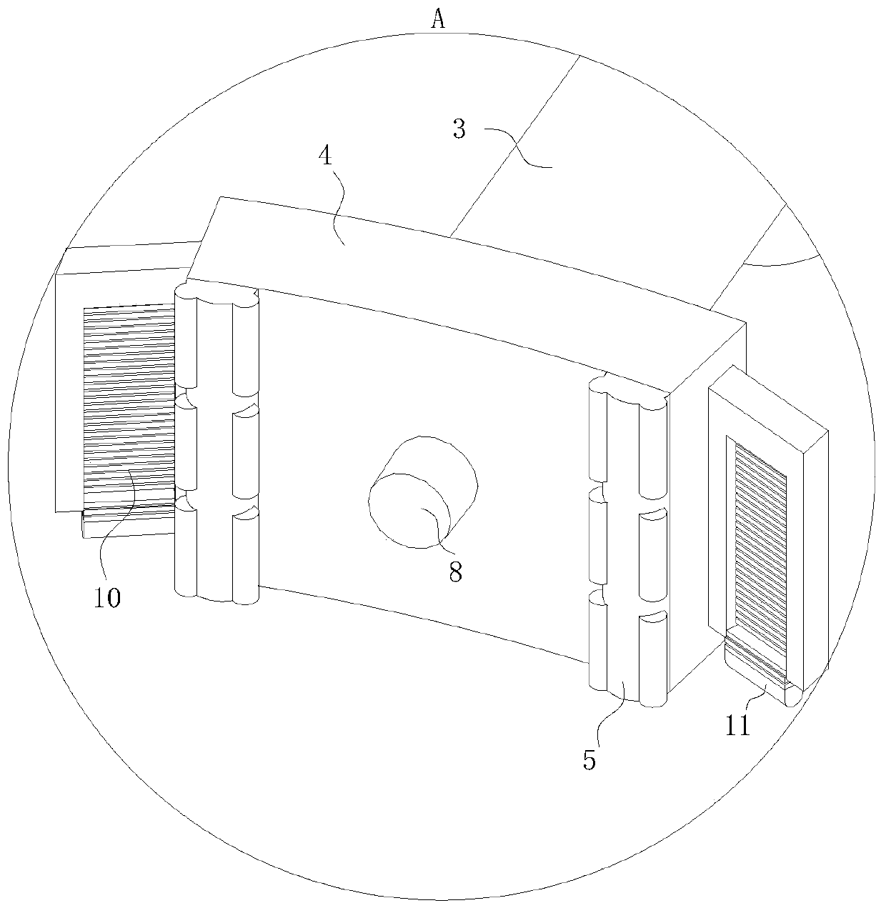
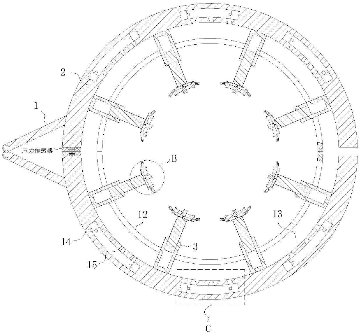
[0027] Such as Figure 1-5 As shown, a crane arm for quick installation according to the present invention includes two connecting arms 1, one end of the two connecting arms 1 is fixedly connected with a peripheral plate 2, and the two peripheral plates 2 form a ring ; The peripheral plate 2 is fixedly connected with a plurality of hydraulic rods 3, and the plurality of hydraulic rods 3 are located inside the circle surrounded by the two peripheral plates 2; the end of the hydraulic rod 3 away from the peripheral plate 2 is fixedly connected with a fixed plate 4. A protruding strip 5 is fixedly connected to the side of the fixing plate 4 away from the hydraulic rod 3;

[0028] The peripheral plate 2 is provided with an auxiliary fixing unit 13 an...


PUM


Abstract

The invention belongs to the technical field of crane equipment, and specifically discloses a crane lifting arm for rapid installation. The crane lifting arm for rapid installation comprises two connection arms, wherein a peripheral plate is fixedly connected to one end of each of the two connection arms separately, and the two peripheral plates encircle a circular ring; a plurality of hydraulic rods are fixedly connected to each peripheral plate, and the plurality of hydraulic rods are located at the inner side of the circular ring encircled by the two peripheral plates; and a fixed plate isfixedly connected to one end away from the corresponding peripheral plate, of each hydraulic plate. According to the crane lifting arm for rapid installation, the two peripheral plates are driven to encircle an iron tower through the two connection arms, wherein after the hydraulic rods are controlled to stretch, the hydraulic rods push the fixed plate to make contact with and be tightly extrudedwith the iron tower, and finally fixing for the iron tower is completed; iron towers with different sizes can be lifted, and moreover, the plurality of hydraulic rods fix the iron tower from the surrounding, the iron tower can be supported by the surrounding regardless of a high speed in a movement process, and the iron tower is in a vertical state, so that the case that the bottom end of the irontower is not easily aligned with an installation base, is prevented, and the installation difficulty is lowered.

Description

technical field [0001] The invention belongs to the technical field of crane equipment, in particular to a crane boom for quick installation. Background technique [0002] The overhead transmission line tower is a structure used to support the conductors and lightning protection lines of high-voltage or ultra-high-voltage overhead transmission lines. In the past, the erection of overhead transmission line iron towers was completed by continuously erecting angle steels one by one. Using this method to erect towers requires a lot of manpower and time. Now there are special cranes for erecting. The iron tower is hoisted and placed, and the lifting arm on the crane is a structure similar to a wrench, which is lifted up after clamping the iron tower. [0003] Because the existing lifting arm is clamped left and right when clamping, when the moving speed is fast, it is easy to make the iron tower tilted. After hoisting to the installation position, the bottom of the iron tower is...

Claims


Application Information

Patent Timeline
Patent Type & Authority Applications(China)
IPC IPC(8): B66C1/44B66C13/08
CPCB66C1/44B66C13/08
Inventor 钱柏融朱良彬周旭东
Owner 淮北亚荣科技有限公司
Why Eureka
Try Eureka