A composite protective structure for slopes

A technology for combining protective structures and slopes, which is applied to underwater structures, infrastructure engineering, buildings, etc., can solve the problems of reducing the seismic force of slopes, inability to resist moderate and strong earthquakes, and insufficient anti-overturning capabilities, and achieve Reduce the sliding force and deformation extrusion force, increase the ability of anti-invasion and anti-slip damage, and increase the effect of anti-slip

Active Publication Date: 2021-07-02
ROCKET FORCE UNIV OF ENG
View PDF7 Cites 0 Cited by
  • Summary
  • Abstract
  • Description
  • Claims
  • Application Information

AI Technical Summary

Problems solved by technology

[0004] After searching, it was found that the published domestic application numbers 201710645357.9, 201811151089.6 and 201810907936.0, although they can play a certain role in shock absorption, still have certain deficiencies. The design of these three patents only partially implements the retaining structure in the middle and lower part of the slope. Shock absorption, for small and micro earthquakes, it cannot resist moderate and strong earthquakes, and the anti-overturning capacity is insufficient; under strong earthquakes, the middle and upper parts of the slope will generate large seismic forces, and the single gravity retaining wall structure cannot reduce the Due to the seismic force generated by the slope, the slope is still facing the danger of instability and damage.

Method used


Image

  • A composite protective structure for slopes
  • A composite protective structure for slopes
  • A composite protective structure for slopes

Examples


Embodiment Construction

[0020] Below in conjunction with accompanying drawing and embodiment the present invention will be further described:

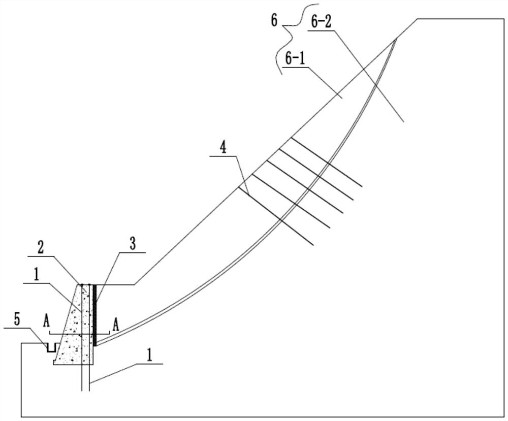
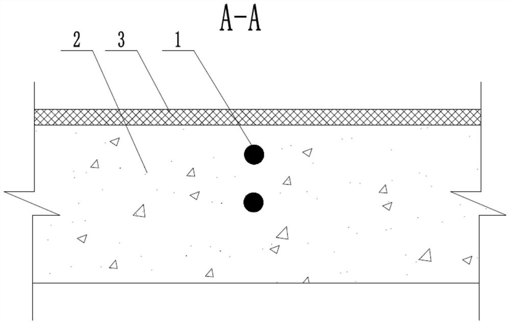
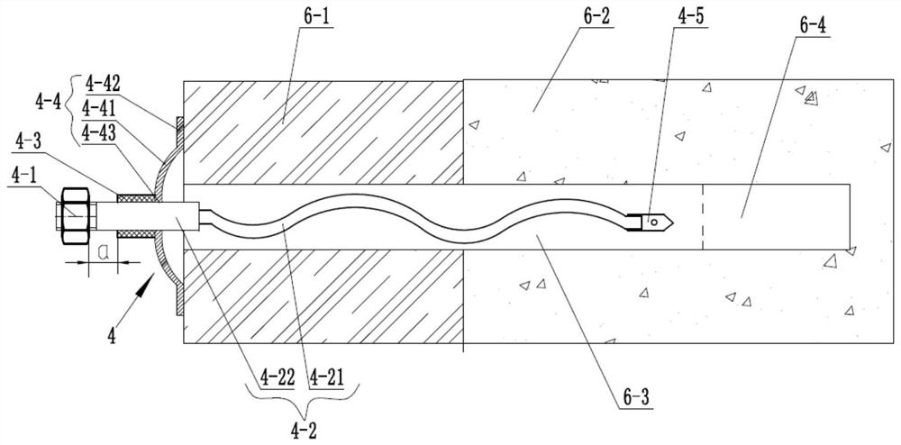
[0021] see Figure 1-4 , a side slope combined protective structure, the side slope combined protective structure is used to be installed on the side slope 6, the side slope combined protective structure includes a common anchor rod 1, a gravity retaining wall 2, a shock absorbing layer 3, a pressure relief Anchor rod 4, drainage ditch 5.

[0022] Specifically, the common anchor 1 can be a common steel wire rope mortar anchor, an inverted wedge metal anchor or a pipe slot anchor, a cement anchor, and the like.

[0023] The slope 6 includes a slope sliding layer 6-1 and a slope bedrock layer 6-2. The slope slide layer 6-1 is geologically different from the slope bedrock layer 6-2.

[0024] The slope sliding layer 6-1 is divided into layers compared with the slope bedrock layer 6-2. When the slope slide layer 6-1 slides down, it slides along the layered lay...


PUM


Abstract

The invention discloses a side slope combined protective structure, which is used to be installed on the side slope, and is characterized in that: the side slope combined protective structure comprises a common anchor rod, a gravity retaining wall and a shock absorption layer , let pressure bolts, drainage ditch; the slope includes slope slip layer and slope bedrock layer; the letdown bolts are inserted on the side slope and extend into the side slope bedrock layer; the The shock-absorbing layer is blocked on the lower side of the slope sliding layer, and the gravity retaining wall is fixed on the lower side of the bedrock layer and is in close contact with the side of the shock-absorbing layer facing away from the slope sliding layer. The ordinary bolt is inserted vertically on the gravity retaining wall and extends downward into the bedrock layer of the side slope. The invention can not only play the role of the gravity retaining wall to bear the earth pressure, but also bear the large deformation under earthquake, and can improve the allowable displacement, anti-slip and anti-overturning ability of the gravity retaining wall, and reduce the gravity retaining wall. The force of the earth wall can avoid damage under the action of strong earthquake.

Description

technical field [0001] The invention relates to the technical field of anti-seismic support for slopes in geotechnical engineering, in particular to a composite protection structure for slopes. Background technique [0002] In the anti-seismic design of slopes, the effects of earthquakes on slope structures mainly lie in two aspects: additional seismic force and displacement. However, the traditional anti-seismic method usually increases the anti-seismic capacity of the structure from the perspective of force, that is, by increasing the stiffness of the structure (such as increasing the size of the structure). However, after the Wenchuan Earthquake, a phenomenon was found that the gravity retaining wall was seriously damaged under the action of a strong earthquake. It is not practical to rely entirely on increasing the cross-sectional size to increase the structural stiffness to resist earthquakes under high-intensity and strong earthquakes. [0003] The main reason is that...

Claims


Application Information

Patent Timeline
Patent Type & Authority Patents(China)
IPC IPC(8): E02D17/20E02D29/02
CPCE02D17/20E02D29/02
Inventor 赖杰刘云王炜高成强张毅袁健
Owner ROCKET FORCE UNIV OF ENG
Why Eureka
Try Eureka