A new energy vehicle brake control device

A new energy vehicle and brake control technology, applied in the field of automobile brakes, can solve problems such as inability to buffer, and achieve good buffering effect, strong bearing capacity, and good protection effect

Active Publication Date: 2020-08-21
宜兴市环湖电器有限公司
View PDF9 Cites 1 Cited by
  • Summary
  • Abstract
  • Description
  • Claims
  • Application Information

AI Technical Summary

Problems solved by technology

[0005] The purpose of the present invention is to provide a new energy vehicle brake control device to solve the problem that the existing brake device cannot buffer when braking

Method used


Image

  • A new energy vehicle brake control device
  • A new energy vehicle brake control device
  • A new energy vehicle brake control device

Examples


Embodiment

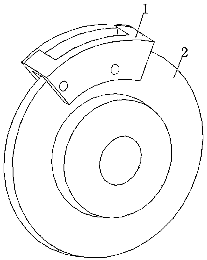
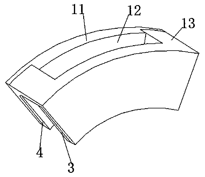
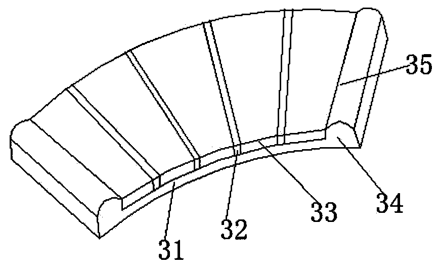
[0038] The brake control device for new energy vehicles in this embodiment includes a brake disc 2, and a brake caliper 1 is sheathed at the outer edge of the brake disc 2; the brake caliper 1 includes a cover plate 11 and an operation frame fixed together by bolts. 13: The second brake disc 4 and the first brake disc 3 are respectively arranged on the side walls of the cover plate 11 and the operation frame 13 close to each other. The first brake disc 3 includes a flat bottom plate 31, and a first positioning block 34 is fixed with bolts at both ends of the bottom plate 31; a strip-shaped friction plate 33 is fixed with bolts on the bottom plate 31; A separator 32 is squeezed between the two friction plates 33; an adjustment member 35 is bound in the first positioning block 34.

[0039] The friction plate 33 includes a steel plate 331 on which a rubber plate 332 is fixed with bolts, and a brake pad 333 is fixed on the upper side of the rubber plate 332 with bolts; a plurality...


PUM


Abstract

The invention discloses a new energy automobile brake control device. The new energy automobile brake control device comprises a brake disc, wherein a brake caliper is arranged on the edge of the outer side of the brake disc in a sleeving mode, the brake caliper comprises a cover plate and an operation frame which are fixed together through a bolt, a second brake disc and a first brake disc are respectively arranged on side walls, close to each other, of the cover plate and the operation frame, the first brake disc comprises a flat-plate-shaped bottom plate, positioning blocks are fixed at twoends of the bottom plate through bolts, long-strip-shaped friction plates are fixed on the bottom plate through bolts, a dummy plate is tightly pressed between each two adjacent friction plates, andan adjustment piece is bound in each positioning block. The second brake disc and the first brake disc realize buffering through an arranged buffering structure in braking, and good protection effectis achieved.

Description

technical field [0001] The invention relates to the technical field of automobile brakes, in particular to a brake control device for new energy automobiles. Background technique [0002] The brake control device plays a key role in the safe driving of the car; when the brake is used for braking, the brake device and the wheel hub of the car perform frictional braking, and the mutual force is relatively large, which will cause serious wear and tear on the brake device. Vibration will occur when braking, which may even cause mechanical damage in severe cases. The shock absorption and buffering effect of the existing braking device is poor, and it cannot protect itself well during braking. [0003] In the Chinese version of the patent with the publication number 201810716860.3, a brake pad structure is disclosed. Although this structure solves the problem of heat dissipation, it lacks a corresponding shock-absorbing buffer structure, and it is difficult to buffer when encount...

Claims


Application Information

Patent Timeline
Patent Type & Authority Patents(China)
IPC IPC(8): F16D65/092F16D69/00F16D69/04
CPCF16D65/0018F16D65/092F16D69/00F16D69/0408F16D2069/007F16D2069/0433
Inventor 付延超
Owner 宜兴市环湖电器有限公司
Why Eureka
Try Eureka